


Gehl Z45, Mustang 450Z Compact Excavator Repair Service Manual
$40.00
Language: English
Format: PDF
Applicable for the Gehl Excavator Model Gehl Z45, Mustang 450Z
- Gehl Z45, Mustang 450Z Excavator Repair Service Manual – 584 Pages
- Gehl Z45, Mustang 450Z Excavator Operators Manual – 228 Pages
- Gehl Z45, Mustang 450Z Excavator Parts Manual – 176 Pages
- Description
- Reviews (0)
Description
Gehl Z45, Mustang 450Z Compact Excavator Repair Service Manual
Language: English
Format: PDF
Applicable for the Gehl Excavator Model Gehl Z45, Mustang 450Z
- Gehl Z45, Mustang 450Z Excavator Repair Service Manual – 584 Pages
- Gehl Z45, Mustang 450Z Excavator Operators Manual – 228 Pages
- Gehl Z45, Mustang 450Z Excavator Parts Manual – 176 Pages
Table of Content of the Gehl Z45, Mustang 450Z Excavator Manual:
CHAPTER 1
General Cautions for Maintenance Work
1-1 Correct Work …………………………………………………………………………………………………………………………………………………….. 1-1
1-2 Safety Precautions …………………………………………………………………………………………………………………………………………….. 1-2
1-3 Preparations……………………………………………………………………………………………………………………………………………………… 1-1
1-4 Cautions for Disassembly and Reassembly…………………………………………………………………………………………………………… 1-1
1-5 Cautions for Removal and Installation of Hydraulic Equipment ………………………………………………………………………………… 1-2
1-6 Cautions for Removal and Installation of Hydraulic Piping……………………………………………………………………………………….. 1-2
1-7 Cautions for Handling Seals………………………………………………………………………………………………………………………………… 1-3
1-8 Correct Installation of Hydraulic Hose …………………………………………………………………………………………………………………… 1-3
1-9 Specifications of Hydraulic Hose………………………………………………………………………………………………………………………….. 1-6
1-10 Air Release of Hydraulic Equipment………………………………………………………………………………………………………………….. 1-11
CHAPTER 2
Technical Data
2-1 Specifications …………………………………………………………………………………………………………………………………………………. 2-1-1
2-2 Outline Drawing and Working Area ……………………………………………………………………………………………………………………. 2-2-1
2-2-1 Canopy type …………………………………………………………………………………………………………………………………………… 2-2-1
2-2-2 Cabin type ……………………………………………………………………………………………………………………………………………… 2-2-2
2-3 Weight List of Main Parts …………………………………………………………………………………………………………………………………. 2-3-1
2-4 Lifting Capacity List …………………………………………………………………………………………………………………………………………. 2-4-1
CHAPTER 3
Service Standards
3-1 Machine Performance ……………………………………………………………………………………………………………………………………… 3-1-1
3-2 Engine …………………………………………………………………………………………………………………………………………………………… 3-2-1
3-3 Undercarriage…………………………………………………………………………………………………………………………………………………. 3-3-1
3-3-1 Rubber Track Specifications …………………………………………………………………………………………………………………….. 3-3-1
3-3-2 Steel Track Specifications ………………………………………………………………………………………………………………………… 3-3-2
3-3-3 Common Specifications of Steel & Rubber Tracks ………………………………………………………………………………………. 3-3-3
3-4 Controls …………………………………………………………………………………………………………………………………………………………. 3-4-1
3-5 Hydraulic Equipment ……………………………………………………………………………………………………………………………………….. 3-5-1
3-5-1 Hydraulic Cylinders …………………………………………………………………………………………………………………………………. 3-5-1
3-6 Implement………………………………………………………………………………………………………………………………………………………. 3-6-1
3-6-1 Front Attachments …………………………………………………………………………………………………………………………………… 3-6-1
3-6-2 Blade Moving Device……………………………………………………………………………………………………………………………….. 3-6-2
3-6-3 Bucket Teeth ………………………………………………………………………………………………………………………………………….. 3-6-2
3-7 List of Tightening Torque………………………………………………………………………………………………………………………………….. 3-7-1
3-7-1 Machine…………………………………………………………………………………………………………………………………………………. 3-7-1
3-7-2 Engine …………………………………………………………………………………………………………………………………………………… 3-7-4
3-7-3 Tightening Torque for General Bolts and Nuts…………………………………………………………………………………………….. 3-7-4
CHAPTER 4
Engine
4-1 General………………………………………………………………………………………………………………………………………………………….. 4-1-1
4-1-1 How to Read This Manual ………………………………………………………………………………………………………………………… 4-1-1
4-1-2 Precautions for Service Work……………………………………………………………………………………………………………………. 4-1-3
4-1-3 Engine External Views ……………………………………………………………………………………………………………………………. 4-1-4
4-1-4 Structural Description ……………………………………………………………………………………………………………………………… 4-1-4
4-1-5 Exhaust Gas Emission Regulation …………………………………………………………………………………………………………….. 4-1-5
4-2 Troubleshooting………………………………………………………………………………………………………………………………………………. 4-2-1
4-2-1 Quick Reference Table for Troubleshooting………………………………………………………………………………………………… 4-2-1
4-2-2 Troubleshooting by Measuring Compression Pressure ………………………………………………………………………………… 4-2-4
4-3 Inspection and Adjustment……………………………………………………………………………………………………………………………….. 4-3-1
4-3-1 Oil Inspection………………………………………………………………………………………………………………………………………….. 4-3-1
4-3-2 Cooling Water Inspection …………………………………………………………………………………………………………………………. 4-3-1
4-3-3 Inspecting Water Leak from Cooling Water System and Radiator ………………………………………………………………….. 4-3-1
4-3-4 Fan Belt Tension Inspection and Adjustment………………………………………………………………………………………………. 4-3-2
4-3-5 Adjusting the Valve Clearance ………………………………………………………………………………………………………………….. 4-3-3
4-3-6 Inspecting the Fuel Injection Valve Injection Pressure and Spray Pattern……………………………………………………….. 4-3-5
4-3-7 Fuel Injection Timing Adjustment / Fuel Injection Pump Inspection and Adjustment …………………………………………. 4-3-9
4-3-8 Sensor Inspection………………………………………………………………………………………………………………………………….. 4-3-12
4-3-9 Battery Inspection………………………………………………………………………………………………………………………………….. 4-3-13
4-3-10 Adjusting Operation……………………………………………………………………………………………………………………………… 4-3-15
4-3-11 Long Storage………………………………………………………………………………………………………………………………………. 4-3-16
4-3-12 Periodic Maintenance Schedule…………………………………………………………………………………………………………….. 4-3-17
4-4 Engine Body…………………………………………………………………………………………………………………………………………………… 4-4-1
4-4-1 Introduction…………………………………………………………………………………………………………………………………………….. 4-4-1
4-4-2 Cylinder Head…………………………………………………………………………………………………………………………………………. 4-4-2
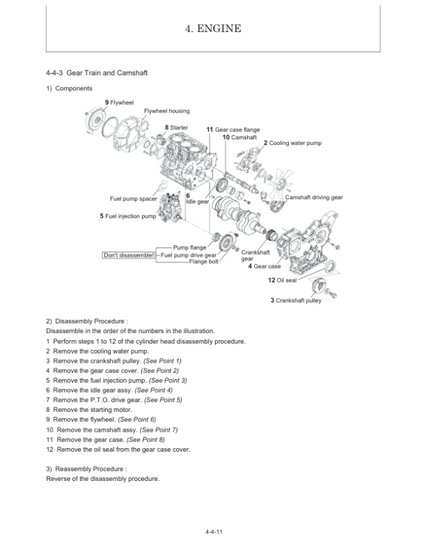
4-4-3 Gear Train and Camshaft……………………………………………………………………………………………………………………….. 4-4-11
4-4-4 Cylinder Block ………………………………………………………………………………………………………………………………………. 4-4-16
4-5 Lubrication System………………………………………………………………………………………………………………………………………….. 4-5-1
4-5-1 Lubrication System Diagram …………………………………………………………………………………………………………………….. 4-5-1
4-5-2 Trochoid pump (4TNV88-BXBV) ……………………………………………………………………………………………………………….. 4-5-2
4-6 Cooling System ………………………………………………………………………………………………………………………………………………. 4-6-1
4-6-1 Cooling Water System……………………………………………………………………………………………………………………………… 4-6-1
4-6-2 Cooling Water Pump Components…………………………………………………………………………………………………………….. 4-6-1
4-6-3 Disassembly (Reverse the Procedure Below for Assembly) ………………………………………………………………………….. 4-6-2
4-6-4 Servicing Points………………………………………………………………………………………………………………………………………. 4-6-2
4-7 Fuel Injection Pump / Governor…………………………………………………………………………………………………………………………. 4-7-1
4-7-1 Introduction…………………………………………………………………………………………………………………………………………….. 4-7-1
4-7-2 Fuel Injection Pump…………………………………………………………………………………………………………………………………. 4-7-1
4-8 Electrical Equipment………………………………………………………………………………………………………………………………………… 4-8-1
4-8-1 Starter Motor ………………………………………………………………………………………………………………………………………….. 4-8-1
4-8-2 Alternator……………………………………………………………………………………………………………………………………………….. 4-8-3
4-8-3 Air Heater ………………………………………………………………………………………………………………………………………………. 4-8-6
CHAPTER 5
Hydraulic System
5-1 Outline …………………………………………………………………………………………………………………………………………………………… 5-1-1
5-1-1 Control Valve Operation …………………………………………………………………………………………………………………………… 5-1-4
5-1-2 Additional Operation of Control Valve ………………………………………………………………………………………………………… 5-1-6
5-2 Hydraulic Circuit Schematic ……………………………………………………………………………………………………………………………… 5-2-1
5-3 Circuit Operation …………………………………………………………………………………………………………………………………………….. 5-3-1
5-3-1 Boom …………………………………………………………………………………………………………………………………………………….. 5-3-1
5-3-2 Arm……………………………………………………………………………………………………………………………………………………….. 5-3-3
5-3-3 Bucket …………………………………………………………………………………………………………………………………………………… 5-3-5
5-3-4 Swing…………………………………………………………………………………………………………………………………………………….. 5-3-7
5-3-5 Boom Swing …………………………………………………………………………………………………………………………………………… 5-3-9
5-3-6 Blade …………………………………………………………………………………………………………………………………………………… 5-3-11
5-3-7 Travel ………………………………………………………………………………………………………………………………………………….. 5-3-13
5-3-8 Non-Deviation Travel (with Boom, Arm or Boom Swing Operation)………………………………………………………………. 5-3-15
5-3-9 Non-Deviation Travel (with Bucket Operation) …………………………………………………………………………………………… 5-3-17
5-3-10 Simultaneous Operation of Boom Up and Arm Retract……………………………………………………………………………… 5-3-19
5-3-11 Simultaneous Operation of Boom Up and Bucket…………………………………………………………………………………….. 5-3-21
5-3-12 Simultaneous Operation of Boom Up and Swing ……………………………………………………………………………………… 5-3-23
5-3-13 Simultaneous Operation of Arm and Bucket ……………………………………………………………………………………………. 5-3-25
5-3-14 Hydraulic P.T.O. ………………………………………………………………………………………………………………………………….. 5-3-27
5-3-15 Quick Coupler……………………………………………………………………………………………………………………………………… 5-3-29
5-4 Pressure Adjustment……………………………………………………………………………………………………………………………………….. 5-4-1
5-4-1 Relief Valves ………………………………………………………………………………………………………………………………………….. 5-4-1
5-4-2 Swing Brake Valve ………………………………………………………………………………………………………………………………….. 5-4-4
5-4-3 Cut-Off Valve………………………………………………………………………………………………………………………………………….. 5-4-5
CHAPTER 6
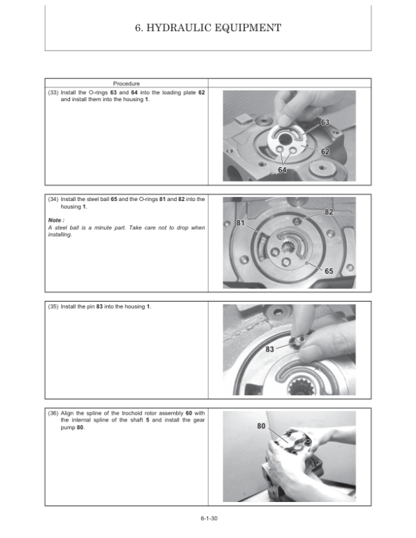
Hydraulic Equipment
6-1 Hydraulic Pump……………………………………………………………………………………………………………………………………………… 6-1-1
6-2 Control Valve………………………………………………………………………………………………………………………………………………….. 6-2-1
6-3 Pilot Valve ……………………………………………………………………………………………………………………………………………………… 6-3-1
6-4 Swing Motor …………………………………………………………………………………………………………………………………………………… 6-4-1
6-5 Travel Motor ………………………………………………………………………………………………………………………………………………….. 6-5-1
6-6 Blade Control Pilot Valve………………………………………………………………………………………………………………………………….. 6-6-1
6-7 Solenoid Valve for P.T.O. Operation ………………………………………………………………………………………………………………….. 6-7-1
6-8 Pilot Check Valve (For Quick Coupler Circuit) …………………………………………………………………………………………………….. 6-8-1
CHAPTER 7
Adjustment and Repair
7-1 Electric Equipment of Machine………………………………………………………………………………………………………………………….. 7-1-1
7-1-1 Parts Layout of Electrical Equipment …………………………………………………………………………………………………………. 7-1-1
7-1-2 Monitor and Alarm Systems ……………………………………………………………………………………………………………………… 7-1-3
7-1-3 Wiring Diagram……………………………………………………………………………………………………………………………………….. 7-1-6
7-1-4 Circuit Description of Engine Start and Stop, and Battery Charging ……………………………………………………………….. 7-1-7
7-1-5 Removal and Reinstallation of Engine ……………………………………………………………………………………………………….. 7-1-9
7-1-6 Removal and Reassembly of Starter Motor ………………………………………………………………………………………………. 7-1-18
7-1-7 Removal and Reassembly of Drive Belts for Generator and Compressor ……………………………………………………… 7-1-19
7-2 Undercarriage…………………………………………………………………………………………………………………………………………………. 7-2-1
7-2-1 Outline …………………………………………………………………………………………………………………………………………………… 7-2-1
7-2-2 Main Parts ……………………………………………………………………………………………………………………………………………… 7-2-1
7-2-3 Points of Reassembly (Rubber Track) ……………………………………………………………………………………………………….. 7-2-2
7-2-4 Points of Reassembly (Steel Track) …………………………………………………………………………………………………………… 7-2-3
7-2-5 Removal and Reinstallation of Track………………………………………………………………………………………………………….. 7-2-4
7-2-6 Removal and Reinstallation of Steel Track …………………………………………………………………………………………………. 7-2-5
7-2-7 Disassembly and Reassembly of Front Idler……………………………………………………………………………………………….. 7-2-8
7-2-8 Disassembly and Reassembly of Track Roller…………………………………………………………………………………………… 7-2-10
7-2-9 Installation of Floating Seal …………………………………………………………………………………………………………………….. 7-2-12
7-2-10 Drawings of Jigs ………………………………………………………………………………………………………………………………….. 7-2-13
7-2-11 Disassembly and Reassembly of Carrier Roller……………………………………………………………………………………….. 7-2-15
7-3 Controls …………………………………………………………………………………………………………………………………………………………. 7-3-1
7-3-1 Control Train…………………………………………………………………………………………………………………………………………… 7-3-1
7-3-2 Mechanical Control Linkage ……………………………………………………………………………………………………………………… 7-3-2
7-3-3 Adjustment of Travel Levers……………………………………………………………………………………………………………………… 7-3-4
7-3-4 Adjustment of Boom Swing Pedal ……………………………………………………………………………………………………………… 7-3-5
7-3-5 Adjustment of Lock Lever…………………………………………………………………………………………………………………………. 7-3-6
7-3-6 Adjustment of Accelerator Lever ……………………………………………………………………………………………………………….. 7-3-7
7-4 Swing Bearing ………………………………………………………………………………………………………………………………………………… 7-4-1
7-5 Hydraulic Equipment ……………………………………………………………………………………………………………………………………….. 7-5-1
7-5-1 Removal and Reinstallation of Hydraulic Pump …………………………………………………………………………………………… 7-5-1
7-5-2 Removal and Reinstallation of Control Valve ………………………………………………………………………………………………. 7-5-3
7-5-3 Removal and Reinstallation of Swing Motor………………………………………………………………………………………………… 7-5-6
7-5-4 Removal and Reinstallation of Swivel Joint…………………………………………………………………………………………………. 7-5-9
7-5-5 Disassembly and Reassembly of Swivel Joint …………………………………………………………………………………………… 7-5-13
7-5-6 Disassembly and Reassembly of Hydraulic Cylinders ………………………………………………………………………………… 7-5-16
7-5-7 Hydraulic Oil Tank …………………………………………………………………………………………………………………………………. 7-5-20
7-5-8 Piping Layout………………………………………………………………………………………………………………………………………… 7-5-26
7-6 Work Implements ……………………………………………………………………………………………………………………………………………. 7-6-1
7-6-1 Removal and Reinstallation of Work Implements…………………………………………………………………………………………. 7-6-1
7-6-2 Quick Coupler……………………………………………………………………………………………………………………………………….. 7-6-10
7-7 Cabin…………………………………………………………………………………………………………………………………………………………….. 7-7-1
7-7-1 Cabin …………………………………………………………………………………………………………………………………………………….. 7-7-1
CHAPTER 8
Periodic Inspection and Servicing
8-1 List of Periodic Inspection and Servicing…………………………………………………………………………………………………………….. 8-1-1
CHAPTER 9
Fuel, Lube Oil and Grease Recommended
9-1 Fuel, Lube Oil and Grease Recommended……………………………………………………………………………………………………………9-1-1
CHAPTER 10
Troubleshooting
10-1 Non-breakdowns …………………………………………………………………………………………………………………………………………. 10-1-1
10-1-1 Natural Release of Bucket…………………………………………………………………………………………………………………….. 10-1-1
10-1-2 Discontinuous Arm Movement ………………………………………………………………………………………………………………. 10-1-1
10-1-3 Drifting of Upperstructure on Quick Travel Operation ……………………………………………………………………………….. 10-1-2
10-1-4 Thermal Shock of Travel Motor ……………………………………………………………………………………………………………… 10-1-3
10-1-5 Elongation of Boom Swing Cylinder on 70 degrees Swing ………………………………………………………………………… 10-1-4
10-1-6 Telescopic Motion of Boom Swing Cylinder with Lock Lever Set to Lock Position ………………………………………… 10-1-5
10-1-7 Time Lag on Travel Speed Switching……………………………………………………………………………………………………… 10-1-6
10-1-8 Fluctuation in Oil Level of Hydraulic Oil Tank Due to Temperature Change…………………………………………………. 10-1-7
10-1-9 Operation of Quick Coupler Cylinder (for Quick Coupler Type) ………………………………………………………………….. 10-1-8
10-2 Troubleshooting…………………………………………………………………………………………………………………………………………… 10-2-1
10-2-1 Machine and Engine…………………………………………………………………………………………………………………………….. 10-2-1
10-2-2 Electrical Equipment on Panel …………………………………………………………………………………………………………….. 10-2-23
CHAPTER 11
Reference Data
11-1 Dimensions and Specifications for Attachment ………………………………………………………………………………………………… 11-1-1
This Service Manual is intended for Gehl Z45, Mustang 450Z Excavator so as to give the owner/operator assistance in preparing, adjusting, maintaining and servicing the machine. More importantly, this manual provides an operating plan for safe and proper use of the machine. Major points of safe operation are
detailed in Chapter 2 – Safety. Read and understand the contents of this manual completely and become familiar with the machine before
attempting to operate it..
Throughout this manual, information is introduced by the word NOTE or IMPORTANT. Be sure to read the message carefully and comply with the message. Following this information will improve operating and maintenance efficiency, help to avoid breakdown and damage and extend the service life of the machine.
Be the first to review “Gehl Z45, Mustang 450Z Compact Excavator Repair Service Manual”
You must be logged in to post a review.


Reviews
There are no reviews yet.