Challenger MT835B, MT845B, MT855B, MT865B, MT875B Tractor Service Manual
$38.00
Challenger MT835B, MT845B, MT855B, MT865B, MT875B Tractor Workshop Manual : 2643 Pages
Format: PDF
Book Number: 79023768
English
Issued October 2005
- Description
- Reviews (0)
Description
Challenger MT835B, MT845B, MT855B, MT865B, MT875B Tractor Service Manual
Manual for: AGCO Challenger MT800B Series Tractor
Format: PDF
Book Number: 79023768
English
Issued October 2005
Challenger MT835B, MT845B, MT855B, MT865B, MT875B Tractor Workshop Manual : 2643 Pages
MT800B Series Manual TABLE OF CONTENTS
- Introduction
- Engine
- Engine Auxiliary
- Powertrain System Operation
- Powertrain Disassembly And Assembly
- Steering And Brake System
- Undercarriage
- Hydraulic And Three Point Hitch Testing And Adjusting
- Hydraulic Schematic
- Electrical Schematics
- Tractor Management System Center (Tmc)
- Auto-guide Systems Operation
- Cab Heating And Air Conditioning
- Component Specifications
- Component Disassembly And Assembly
- Troubleshooting
MT835B, MT845B, MT855B, MT865B, MT875B Manual Extract
Adjusting Belt Alignment
Introduction
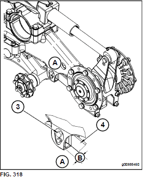
FIG. 318: A drawing of the right side of the undercarriage is shown.
By adjusting the bolt (3) and the corresponding bolt on the opposite side of the lever (4), you can adjust the alignment of the guide blocks to the midwheels.
Dimension (B) and the corresponding dimension on the other side of the lever (4) will determine the alignment of the guide blocks to the midwheels.
When dimension (B) is smaller, the guide blocks will track closer to the outside midwheels. When dimension (B) is larger, the guide blocks will track closer to the inside midwheels.
Procedure to Adjust the Belt Alignment Use the following steps to cause the guide blocks to ride closer to the outside midwheels: NOTE: Do not turn the adjusting bolts by more than 1/4 turn.
1. Move the tractor to a smooth horizontal location.
Move away from working tractors and personnel.
Lower implements and lower the three-point hitch to the ground.
2. Move the transmission control lever to the PARK position.
3. Turn off the engine.
FIG. 319: Photo of the right side of the undercarriage.
4. Remove the bolt (5).
5. Remove the lock plate (6).
6. Remove the corresponding small bolt and the lock plate on the opposite side of the frame.
7. Loosen the corresponding large bolt on the other side of the frame by 1/4 turn. (Turn the bolt counterclockwise.)
8. Tighten the bolt (3) to a torque of 200 N∙m (150 lb ft).
9. Install the lock plate (6) and the bolt (5).
10. Install the corresponding lock plate and the small bolt on the other side of the frame.
Use the following steps to cause the guide blocks to ride closer to the inside midwheels: NOTE: Do not turn the adjusting bolts by more than 1/4 turn.
11. Remove lock plate (6) and bolt (5).
12. Loosen bolt (3) by 1/4 turn. (Turn the bolt counterclockwise.)
13. Remove the corresponding small bolt and the lock plate from the other side of the frame.
14. Tighten the corresponding bolt on the other side of the frame to a torque of 200 N∙m (150 lb ft).
15. Install the lock plate and the small bolt on the other side of the frame.
16. Install lock plate (6) and bolt (5).
17. Check the belt alignment again.
Reference: Refer to Checking Belt Alignment in this section.
18. Repeat Step 4 through Step 16 until the belt alignment is correct.
Be the first to review “Challenger MT835B, MT845B, MT855B, MT865B, MT875B Tractor Service Manual”
You must be logged in to post a review.









Reviews
There are no reviews yet.