
Case WX148 Wheeled Excavator Service Manual
$36.00
Manual Included:
• Service Manual: 1177 Pages
Specifications:
• Brand: Case
• Model: WX148
• Type: Excavator
• Manuals: Service Manual
• Publication Numbers: 47500167 (Jan 2013) and 48005353 (Apr 2016)
• Language: English
• Format: PDF
- Description
- Reviews (0)
Description
Table of Contents
- Content
- Introduction
- Engine
- Transmission
- Four Wheel Drive
- Front Axle
- Rear Axle
- Brakes and Controls
- Hydraulic System
- Frames and ballasting
- Steering
- Wheels
- Cab climate Control
- Electrical System
- Boom, dippers and arm
- Platform, cab, bodywork and decals
- Special Index Tool
- Engines
- Fuel System
- Electrical
- Track and Suspension
- Power Train
- Hydraulics
- Mounted Equipment
Manual Extract Inspection
 Removal and installation of slewing gearbox Park the machine on a level and firm surface.
Lower the attachment to the ground.
Lower the blade and the stabilizers to the ground.
Engage the parking brake.
Lock the upper structure.
Stop the engine.
Move both hydraulic control levers in all directions, to release possible residual pressure inside the hydraulic system.
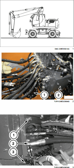
In order to remove the slewing gearbox (1) from its seat, it is necessary to remove the main valve (2).
Gain access to the main valve by climbing the relevant machine plate from the left.
Remove any residual pressure from the hydraulic tank by using the breather valve.
ATTENTION: The procedure provides for the disconnection of the hydraulic lines which can contain a certain amount of hydraulic oil. Adequately protect yourself from contact.
Adequately mark the lines to be disconnected from the main valve for a subsequent reassembly.
Disassemble all hydraulic lines (2) from the main valve installed on the upper side, on the arm’s side and on the engine’s side. Install plugs to prevent the escape of the oil trapped inside the main valve and a possible introduction of dust and/or dirt.
Moreover, on the engine side, disconnect all electric connections (3) after adequately marking them for a subsequent reassembly. Sling the main valve and loosen the 3 screws (1) which fasten it to the supporting bracket. After checking that no lines or electric cables interfere with the assembly to be removed, lift the assembly.
NOTICE: Slowly lift the main valve, and avoid hitting the surrounding components.
Be the first to review “Case WX148 Wheeled Excavator Service Manual”
You must be logged in to post a review.
Reviews
There are no reviews yet.