
Case JX60, JX70, JX80, JX90, JX95 Tractor Service Manual
$34.00
Manual Included:
• Repair Manual: 708 pages
Specifications:
• Brand: Case
• Model: JX60, JX70, JX80, JX90, JX95
• Type: Tractor
• Manuals: Repair Manual
• Publication Number: 87649371 (Mar 2007)
• Language: English
• Format: PDF
- Description
- Reviews (0)
Description
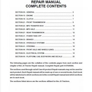
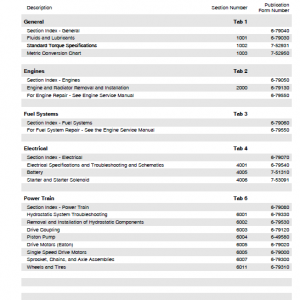
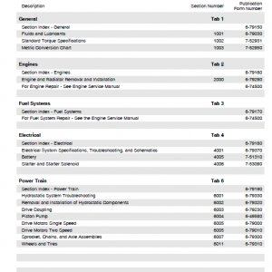
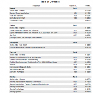
Table of Contents
SECTION 00 – GENERAL . . . . . . . . . . . . . . . . . . . . . . . . . . . . . . . . . . . . . . . . . . . . 2
SECTION 10 – ENGINE . . . . . . . . . . . . . . . . . . . . . . . . . . . . . . . . . . . . . . . . . . . . . . 2
SECTION 18 – CLUTCH . . . . . . . . . . . . . . . . . . . . . . . . . . . . . . . . . . . . . . . . . . . . . . 7
SECTION 21 – FRONT TRANSMISSION . . . . . . . . . . . . . . . . . . . . . . . . . . . . . . . 8
SECTION 23 – MFD TRANSFER BOX . . . . . . . . . . . . . . . . . . . . . . . . . . . . . . . . . 10
SECTION 25 – MFD AXLE . . . . . . . . . . . . . . . . . . . . . . . . . . . . . . . . . . . . . . . . . . . . 11
SECTION 27 – REAR TRANSMISSION . . . . . . . . . . . . . . . . . . . . . . . . . . . . . . . . . 12
SECTION 31 – POWER TAKE-OFF . . . . . . . . . . . . . . . . . . . . . . . . . . . . . . . . . . . . 13
SECTION 33 – BRAKES . . . . . . . . . . . . . . . . . . . . . . . . . . . . . . . . . . . . . . . . . . . . . . 14
SECTION 35 – HYDRAULIC SYSTEMS . . . . . . . . . . . . . . . . . . . . . . . . . . . . . . . . 15
SECTION 41 – STEERING . . . . . . . . . . . . . . . . . . . . . . . . . . . . . . . . . . . . . . . . . . . . 18
SECTION 44 – FRONT AXLE AND WHEELS (2WD) . . . . . . . . . . . . . . . . . . . . . 19
SECTION 55 – ELECTRICAL SYSTEM . . . . . . . . . . . . . . . . . . . . . . . . . . . . . . . . . 19
SECTION 90 – PLATFORM, CAB, BODYWORK AND DECALS . . . . . . . . . . . 25
The following pages are the collation of the contents pages from each section and chapter of the JX Tractor Repair manual. Complete Repair Manual# 87649366.
Manual Extract: SERVICE BRAKES
The service brakes are hydraulic with oil bath discs.
The two control pumps (one for each pedal) are housed in the front section of the cab and are connected to their respective pedals by means of two rods.
These pumps can be actuated either independently or together. If actuated together, the pedals are connected by a pin.
A connecting pipe between the two pumps ensures balanced braking even when the brake discs are not equally worn.
The two control pumps are fed from a single tank located above the pumps.
Refer to the illustrations on page 5.
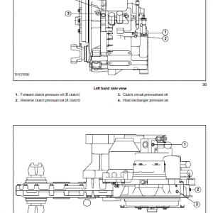
The service brakes are slave cylinder operated. When the left–hand brake pedal (fig. a ) is depressed, the master cylinder (MS) sends the oil to the slave cylinder (SL). The brake links (1) move as indicated by the arrows, by the help of slave cylinder (SL) this causing actuator discs to turn, ball (3) in the tapered seats to force the discs apart as shown in detail (c).
As a result, two simultaneous actions compress the brake discs against the differential support (8) and the back up discs, immediately upon releasing the pedal spring (7), pull the actuator (4) back into the rest position (figure b and detail d) and as a result the discs are released. The action is similar when the right–hand brake pedal is pressed (Rd).
The brake discs (one for each rear wheel) are positioned between the rear transmission box and the lateral final drive box and are splined onto the differential output half–shafts.
Be the first to review “Case JX60, JX70, JX80, JX90, JX95 Tractor Service Manual”
You must be logged in to post a review.
Reviews
There are no reviews yet.