
Case 250, 280, 310, 340, 380, 400 Magnum AFS Connect Service Repair Manual
$99.00
Manual Included:
- Service Repair Manual: 23825 pages
Specifications:
- Brand: Case
- Model:
250 AFS Connect,
280 AFS Connect,
310 AFS Connect,
340 AFS Connect,
380 AFS Connect,
400 AFS Connect - Type: Magnum Tractor
- Serial: JJAM*****KRK02669 till JJAM*****PRK06000 (covers KR, LR, MR, NR, OR, PR)
- Manuals: Service Repair Manual
- Publication Numbers: 92648350 (October 2024)
- Language: English
- Format: PDF
- Description
- Reviews (0)
Description
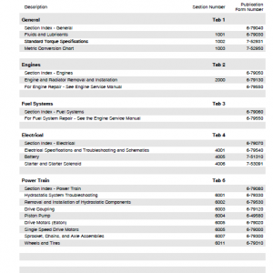
Table of Contents – Case 250, 280, 310, 340, 380, 400 Magnum AFS Connect
- Contents
- Introduction
- Engine
- Power Coupling
- Transmission
- Four Wheel Drive (4WD) System
- Rear Axle System
- Power Take Off (PTO)
- Brakes and Controls
- Hydraulic System
- Hitches, drawbars and implement couplings
- Frames and ballasting
- Steering
- Wheels
- Cab Climate Control
- Electrical Systems
- Platform, Cab, bodywork and decals
- Special Tool Index
- Electrical Schematic
- Hydraulic Schematic
Manual Extract: Hydraulic systems – Overheating
Cause:
The hydraulic system is overheating and alarm is visible in the display.
Possible failure modes:
1. Hydraulic Flow setting set too high
2. Oil cooler external malfunctions
3. Incorrect oil level
4. Incorrect oil
5. Oil degradation
6. Thermal bypass valve failure
7. Obstruction in the oil cooler system
8. Incorrect pump pressure
1. Hydraulic flow settings set too high causing function to go into relief and/or generate unnecessary heat to the hydraulic circuit. Disconnect any hydraulic powered attachments. Operate machine and check for hydraulic overheating.
A. Hydraulic oil not overheating. Set hydraulic flow to the minimum flow setting that allows hydraulic function to operate for desired task.
B. Hydraulic oil still overheating. Go to Step2.
2. Check the oil cooler system for obstructions. Check for any debris or dirt in the radiator, the screen, or other parts to make sure there is a correct air flow through the cooling system.
A. Obstructions exist in the cooling system. Remove the obstructions blocking air flow through the cooling system. Return the unit to normal operation.
B. No obstructions exist in the cooling system. Go to Step3.
3. Ensure that there is the correct amount of oil in the hydraulic system. Check the level of transmission oil. Refer to the Operator Manual.
A. The oil level is low. Add oil until the correct level is achieved. Return the unit to normal operation.
B. The oil level is correct. Go to Step4.
4. Check that you have the recommended oil with the correct specifications in your hydraulic system. Refer to the Operator Manual for the correct specification.
A. Incorrect oil is in the unit. Drain and replace the oil. Use oil that meets or exeeds the recommended specification. Return the unit to normal operation.
B. The correct oil is in the unit. Go to Step5.
5. Check that the oil change interval has not been exceeded. Refer to the Operator Manual for the correct service interval.
A. The oil service interval has been exceeded. Drain and refill the oil. Use new oil meeting or exceeding the recommended specifications. Return the unit to normal operation.
B. The oil is within the recommended service interval. Go to Step6.
6. Start the engine and check if the thermal bypass valve functions correctly. The thermostat should start to open when the temperature of the coolant is at about 65 °C (149 °F). The thermostat should be completely open at about 90 °C (194 °F). Use a laser thermometer to check the temperatures of the tubes just before and just after the thermostat. See: Thermal bypass valve – Component identification (35.300)
A. The thermal bypass valve fails to activate. Repair or replace the thermal bypass valve. Return the unit to normal operation.
B. The thermal bypass valve operates correctly. Go to Step7.
7. Check for an internal blockage in the hydraulic hoses or the hydraulic oil cooler.
A. A blockage exists in the system. Remove the blockage and clean or replace any required parts. Return the unit to normal operation.
B. No blockage is found. Go to Step8.
8. Perform the combination pump pressure test. See: Combination pump units – Pressure test – Charge and lubrication pump (35.304)
A. The pump pressure is low. Go to Step9
B. The pump pressure is correct. Escalate a request to the Technical Help Desk (THD). Include the combination pump pressure test results in the request.
9. Inspect the charge/lube relief valve.
A. Charge/lube relief valve is damaged or stuck open. Repair or replace the charge/lube relief valve. Return the unit to normal operation.
B. Charge/lube relief valve is operating correctly. Go to Step10.
10. Inspect the inlet suction screen for debris or blockage.
A. Inlet suction screen is blocked. See Reservoir, cooler, and filters – Plugging – Debris found in suction screen or hydraulic filter (RST/RDV) (35.304).
B. Inlet suction screen is clear and unobstructed. Escalate a request to the Technical Help Desk (THD).
Be the first to review “Case 250, 280, 310, 340, 380, 400 Magnum AFS Connect Service Repair Manual”
You must be logged in to post a review.
Reviews
There are no reviews yet.