
Toro Reelmaster 3100-D (SN 403430000 and Below) Service Repair Manual
$34.00
Manual Included:
- Service Repair Manual: 348 Pages
Specifications:
- Brand: Toro
- Model: Reelmaster 3100-D (SN 403430000 and Below)
- Type: Large Reel Mowers
- Manuals: Service Repair Manual
- Publication Numbers: 99024SL
- Language: English
- Format: PDF
- Description
- Reviews (0)
Description
Table of Content – Reelmaster 3100-D (SN 403430000 and Below)
- Title Page
- Revision History
- Reader Comments
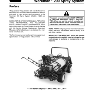
- Preface
- Table Of Contents
- 1 – Safety
- General Safety Instructions
- Before Operating
- While Operating
- Maintenance and Service
- Jacking Instructions
- Safety and Instruction Decals
- 2 – Product Records and Maintenance
- Product Records
- Maintenance
- Equivalents and Conversions
- Torque Specifications
- Lubrication
- Preparation for Seasonal Storage
- 3 – Kubota Diesel Engine
- Introduction
- Specifications
- General Information
- Check Engine Oil
- Fill Fuel Tank
- Check Cooling System
- Adjustments
- Adjust Throttle Cable
- Adjust Alternator, Fan Belt
- Service and Repairs
- Change Engine Oil and Filter
- Replace Traction Belt
- Bleed Fuel System
- Bleed Air from Fuel Injectors
- Muffler and Air Cleaner
- Water, Fuel Separator
- Fuel System
- Radiator
- Engine Removal and Installation
- Kubota 05 Series Workshop Manual (S.N below 250000000)
- Kubota 05-E2B Series Workshop Manual (S.N 250000001-270999999)
- Kubota 05-E3B Series Workshop Manual (S.N 280000001 – 399999999)
- Kubota 05-E4B Series Workshop Manual (S.N 400000001 and up)
- 4 – Hydraulic System
- Specifications
- General Information
- Hydraulic Hoses
- Hydraulic Fitting Installation
- Towing Traction Unit
- Check Hydraulic System Fluid
- Relieving Hydraulic System Pressure
- Traction Circuit (Closed Loop) Component Failure
- Hydraulic Schematics
- Model 03200
- Model 03201
- Models 03206 and 03170
- Models 03207 and 03171
- Hydraulic Flow Diagrams
- Traction Circuits
- Reel Circuit
- Lift Circuit (Up)
- Lift Circuit (Down)
- Sidewinder Circuit
- Steering Circuit
- Special Tools
- Troubleshooting
- Testing
- Precautions for Hydraulic Testing
- Traction Circuit Working Pressure Test
- Piston Pump (P3) Flow and Traction Relief Pressure Test
- Charge Relief Valve Pressure Test
- Gear Pump (P2) Flow Test
- Wheel Motor Efficiency Test
- Reel Circuit Pressure Test
- Gear Pump (P1) Flow Test
- Manifold Relief Valve (R1) Pressure Test
- Reel Motor Efficiency Ł Case Drain Test
- Reel Motor CrossŁover Relief Pressures Test
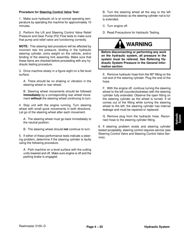
- Lift and Steering Control Valve Relief Pressure Test
- Steering Control Valve Test
- Adjustments
- Adjust Traction Drive for Neutral
- Adjust Manifold Relief Valve
- Service and Repairs
- General Precautions for Removing and Installing Hydraulic System Components
- Change Hydraulic Fluid
- Replace Hydraulic Oil Filter
- Replace Traction Belt
- Check Hydraulic Lines and Hoses
- Flush Hydraulic System
- Charge Hydraulic System
- Hydraulic Tank and Hydraulic Oil Filter
- Front Wheel Motors
- Rear Wheel Motor
- Wheel Motor Service
- Reel Motors
- Reel Motor Service (Eaton)
- Reel Motor Service (Casappa)
- Oil Cooler
- Hydraulic Manifold
- Hydraulic Manifold Service
- Control Valve (Models 03200, 03206 and 03170)
- Control Valve Service (Models 03200, 03206 and 03170)
- Control Valve (Models 03201, 03207 and 03171)
- Control Valve Service (Models 03201, 03207 and 03171)
- Piston Pump
- Neutral Arm Assembly
- Piston Pump Removal
- Piston Pump Installation
- Piston Pump Service
- Piston Pump Crush Ring Replacement
- Sidewinder (Models 03201, 03207 and 03171)
- Steering Control Valve
- Steering Control Valve Service (S.N 90101 to 230999999)
- Steering Control Valve Service (S.N 240000001 and up)
- Gear Pump
- Gear Pump Service
- Disassembly
- Inspection
- Reassembly
- Front Lift Cylinder
- Rear Lift Cylinder
- Lift Cylinder Service
- Steering Cylinder
- Steering Cylinder Service
- Ross Torqmotor Wheel Motor Service Repair Manual (S.N below 260999999)
- Parker Torqmotor Wheel Motor Service Repair Manual (S.N 270000000 and up)
- Eaton Piston Pump Repair Information
- Ross Hydraguide Steering Control Service Repair Manual
- Danfoss Steering Control Service Repair Manual
- 5 – Electrical System
- Schematics and Diagrams
- (S.N 901201 – 901050)
- Glow Circuits
- Crank Circuits
- Run Circuits (Transport
- Run Circuits (Mow)
- Run Circuits (Backlap)
- Wiring Diagram
- Wire Identification Chart
- (S.N 90151 to 230999999)
- Glow Circuits
- Crank Circuits
- Run Circuits (Transport)
- Run Circuits (Mow)
- Run Circuits (Backlap)
- Wiring Diagram
- Wire Identification Chart
- Harness Diagram
- (S.N 240000001 and up)
- Wiring Diagram
- Harness Diagram
- (Serial Numbers 314000001 to 403430000)
- Wiring Diagram
- Wire Harness Diagram
- (Serial Numbers Above 403430001)
- Wiring Diagram
- Wire Harness Diagram
- Special Tools
- Troubleshooting
- Starting Problems
- General Run and Transport Problems
- Cutting Unit Operating Problems
- Electrical System Quick Check
- Battery Test (Open Circuit Test)
- Charging System Test
- Glow Plug System Test
- Check Operation of Interlock Switches
- Component Testing
- Ignition Switch
- Glow Relay
- Start, Seat, and High Temperature Shutdown Relays
- Hour Meter
- Reel Drive Solenoid
- High Temperature Warning and Shutdown Switches
- Diode Assemblies
- Warning Light Cluster (S.N Below 240000000)
- Indicator Lights (S.N Above 240000000)
- Fuel Pump
- Fuel Stop Solenoid (Solenoid With 3 Wire Connector)
- Fuel Stop Solenoid (Solenoid With 2 Wire Connector)
- Glow Controller
- Standard Control Module
- Service and Repairs
- Battery Storage
- Battery Care
- Battery Service
- 6 – Wheels, Brakes, and Miscellaneous
- Specifications
- Special Tools
- Adjustments
- Adjust Brake
- Service and Repairs
- Standard Seat
- Deluxe Seat
- Front Wheel and Brake
- Rear Fork and Wheel
- Brake Linkages
- Steering Column
- 7 – SPA Cutting Units
- Table of Contents
- Specifications
- Special Tools
- Gauge Bar Assembly
- Handle Assembly – TOR299100
- Bedknife Screw Tool – TOR510880
- Bedknife Top Angle Indicator and Mount
- Troubleshooting
- Factors That Can Affect Quality of Cut
- Adjustments
- Characteristics
- Daily Adjustments
- Adjust Bedknife Parallel to Reel
- Set Height-of-Cut and Level Both Rollers
- Verify Height-of-Cut and Front Roller Level
- Adjust Front Lift Arms
- Adjust Rear Lift Arm
- Service and Repairs
- Greasing Bearings, Bushings, and Pivot Points
- Backlapping
- Cutting Unit Removal and Installation
- Reel Motor Removal and Installation
- Reel Removal and Bearing Replacement
- Bedbar Removal and Installation
- Bedknife Replacement and Grinding
- Roller Removal and Installation
- Roller Bearing and Seal Replacement
- Prepare Reel for Grinding
- Fixed Side Plate Installation
- Front Lift Arms
- Rear Lift Arm
- Skid Kit Installation
- Carrier Frame
- 8 – DPA Cutting Units
- Table of Contents
- Specifications
- General Information
- Cutting Unit Operator's Manual
- Special Tools
- Gauge Bar Assembly
- Bedknife Screw Tool
- Handle Assembly
- Plastic Plug
- Cutting Unit Kickstand
- Spline Insert Tool
- Diameter, Circumference Measuring Tape
- Roller Rebuild Kit
- Turf Evaluator Tool
- Reel Bearing Installation Tool (cutting units with painted side plates)
- Cutting Reel Shim
- Cutting Performance Paper
- Pulley Alignment Tool
- Bedknife Top Angle Indicator and Mount
- Factors That Can Affect Cutting Performance
- Adjustments
- Characteristics
- Reel Bearing Adjustment (cutting units with painted side plates)
- Leveling Rear Roller
- Service and Repairs
- Hydraulic Reel Motor
- Backlapping
- Bedbar Assembly
- Bedknife Replacement and Grinding
- Bedbar Adjuster Service
- Reel Assembly (cutting units with painted side plates)
- Reel Assembly Service (cutting units with painted side plates)
- Reel Assembly (cutting units with aluminum side plates)
- Reel Assembly Service (cutting units with aluminum side plates)
- Preparing Reel for Grinding
- Front Roller
- Rear Roller
- Roller Service
- Rear Roller Brush – Optional (cutting units with painted side plates)
- Rear Roller Brush – Optional (cutting units with aluminum side plates)
- 9 – Universal Groomer – DPA Cutting Units (Optional)
- Table of Contents
- Grooming Performance
- Troubleshooting
- Groomer Reel Mechanical Problems
- Service and Repairs
- Gear Box Assembly
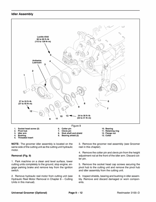
- Idler Assembly
- Groomer Reel
- Groomer Reel Service
- Grooming Brush (Optional) Service
- Height Adjuster Assembly
Be the first to review “Toro Reelmaster 3100-D (SN 403430000 and Below) Service Repair Manual”
You must be logged in to post a review.

Reviews
There are no reviews yet.