
Toro Outcross 9060 Service Repair Manual
$34.00
Manual Included:
- Service Repair Manual: 472 Pages
Specifications:
- Brand: Toro
- Model: Outcross 9060
- Type: Vehicles
- Manuals: Service Repair Manual
- Publication Numbers: 18234SL
- Language: English
- Format: PDF
- Description
- Reviews (0)
Description
Table of Content – Outcross 9060
- Revision History
- Reader Comments
- Preface
- Service Procedure Icons
- Chapter 1 : Safety
- Safety Instructions
- Supervisor’s Responsibilities
- Before Operating the Machine
- Operating the Machine
- Maintenance and Service
- Jacking Instructions
- Raising the Front of the Machine
- Raising the Rear of the Machine
- Safety and Instructional Decals
- Chapter 2 : Specifications and Maintenance
- Specifications
- Overall Dimensions
- Traction Unit
- Engine
- Hydraulic System
- Traction and PTO Drive
- Chassis
- Torque Specifications
- Calculating the Torque Values When Using a Drive-Adapter Wrench
- Identifying the Fastener
- Standard Torque for Dry, Zinc Plated, and Steel Fasteners (Inch Series)
- Standard Torque for Dry, Zinc Plated, and Steel Fasteners (Metric Fasteners)
- Other Torque Specifications
- Conversion Factors
- Shop Supplies
- Special Tools
- Chapter 3 : Troubleshooting
- GEARS – The Systematic Approach to Defining, Diagnosing and Solving Problems
- Gather Information
- Evaluate Potential Causes
- Assess Performance
- Repair
- Solution Confirmation
- Operator Advisories
- Machine and Engine Faults
- Using the InfoCenter display for Troubleshooting
- TRACTION (example):
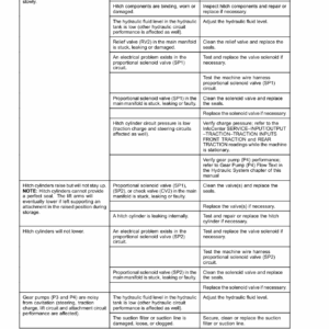
- General Hydraulic System Problems
- Traction System Problems
- Steering System Problems
- PTO System Problems
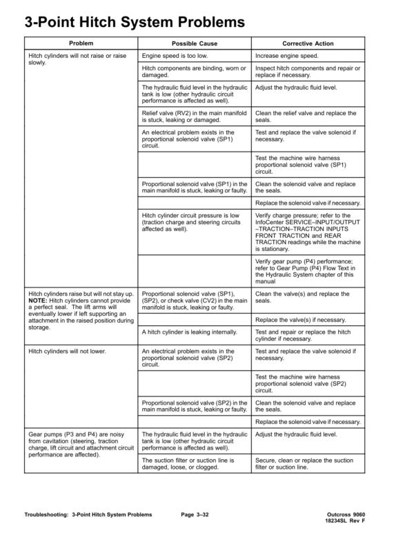
- 3-Point Hitch System Problems
- Attachment, Loader Problems
- Chapter 4 : Engine
- General Information
- Traction Unit Operator’s Manual
- Yanmar Service and Troubleshooting Manuals
- Shutting Off the Engine
- Engine Electronic Control Unit (ECU)
- Yanmar Engine
- Diesel Particulate Filter
- Service and Repairs
- Air Cleaner System
- Exhaust System
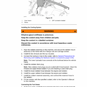
- Radiator
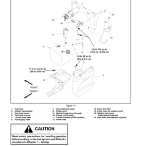
- Fuel System
- Engine
- Flywheel Housing and Drive Coupler
- Chapter 5 : Hydraulic System
- General Information
- Traction Unit Operator’s Manual and Accessory Installation Instructions
- Relieving Pressure from the Hydraulic System
- Towing the Traction Unit
- Traction Circuit (Closed-Loop) Component Failure
- Hydraulic Hoses
- Installing O-rings
- Installing Hydraulic Hoses and Tubes (O-Ring Face Seal)
- Installing the Hydraulic Fittings (SAE Straight Thread O-Ring Fittings)
- Hydraulic Schematic
- Hydraulic Flow Diagrams
- Traction Circuit
- Steering Circuit
- Hitch Cylinder Circuit
- Brake Circuit
- Differential Lock Circuit
- PTO Clutch Circuit
- Attachment Circuit
- Front Loader Circuit
- Selector Control Valve (SCV) Circuit (optional)
- Testing the Hydraulic System
- Hydraulic Test Selection
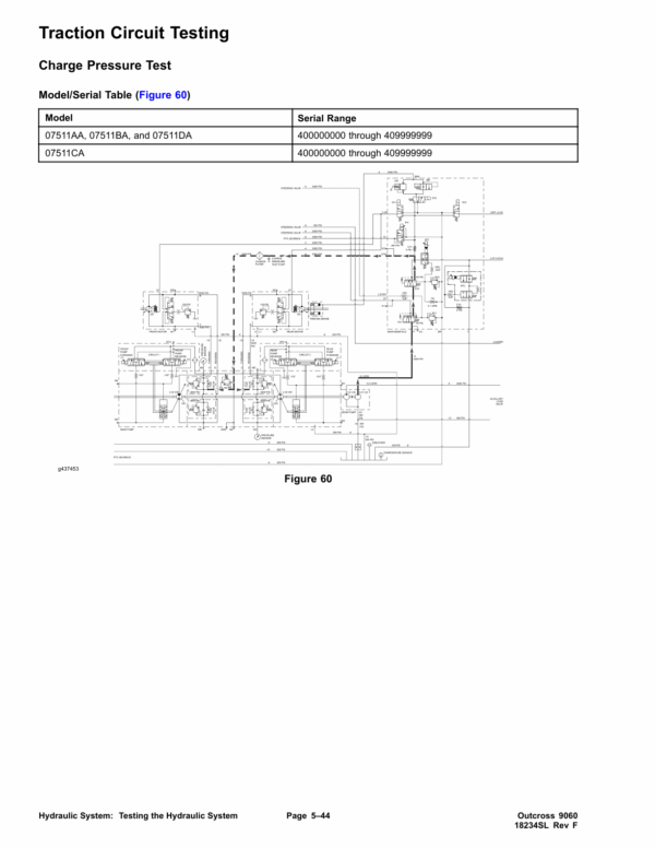
- Traction Circuit Testing
- Steering, Hitch Cylinder Circuit Testing – Steering Relief Valve (RV1) Pressure Test
- Steering, Hitch Cylinder Circuit Testing – Hitch Cylinder Relief Valve (RV2) Pressure Test
- Steering, Hitch Cylinder Circuit Testing – Gear Pump (P4) Flow
- Attachment, Loader Circuit Testing – Relief Valve Pressure Test
- Attachment, Loader Circuit Testing – Gear Pump (P3) Flow Test
- Service and Repairs
- General Precautions for Removing and Installing the Hydraulic System Components
- Checking the Hydraulic Lines and Hoses
- Flushing the Hydraulic System
- Filtering the Closed-Loop Traction Circuit
- Priming the Hydraulic Pumps
- Charging the Hydraulic System
- Hydraulic Tank
- Hydraulic Fluid Cooler
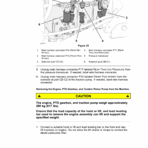
- Tandem Piston (Traction) Pump (P1) and (P2)
- Tandem Piston (Traction) Pump (P1) and (P2) Service
- Gear Pump (P3) and (P4)
- Gear Pump (P3) and (P4) Service
- Axle Motors
- Axle Motor Service
- Axle Differential Locks
- Hydraulic Brake Assembly
- Hydraulic Brake Service
- Main Hydraulic Manifold
- Main Manifold Service
- Cartridge Valve Service
- Steering Control Valve
- Steering Control Valve Service
- Steering Cylinders
- Steering Cylinder Service
- 3-Point Hitch Cylinders
- 3-Point Hitch Cylinder Service
- PTO Clutch
- Auxiliary Load Valve
- Auxiliary Load Valve Service
- Front Loader Control Valve
- Front Loader Control Valve Service
- Selector Control Valve Manifolds (optional)
- Selector Control Valve Manifold (optional) Service
- Chapter 6 : Electrical System
- General Information
- Traction Unit Operator’s Manual and Accessory Installation Instructions
- Yanmar Engine Electrical Components
- InfoCenter Display
- Primary Controller (T1: TEC)
- Status Display Controller (T2: TDM)
- Engine Electronic Control Unit (ECU)
- InchMode Controller (T3: TEC) (optional)
- CAN bus Communications
- Electrical Drawings
- Electrical System Quick Checks
- Testing the Charging System
- Checking the Operation of the Interlock Switches
- Electrical Component Testing
- Fuses
- Fusible Link Harness
- CAN bus
- Primary Controller (T1: TEC)
- Status Display Controller (T2: TDM)
- InchMode Controller (T3: TEC) (optional)
- Key Switch
- Mode Selector
- Parking Brake Switch
- Power Take Off (PTO) Enable Switch
- Economy (ECO) Mode Switch
- Hydraulic Auxiliary (AUX) Switch
- Seat Switch
- Paddle (3-Point Hitch) and Transmission Lever Switches
- Headlight, Work Light Switch
- Cruise Control Off, On, Set Switch
- Cruise Control Speed Increase, Decrease Switch
- Air Conditioning On, Off Switch
- Heater, Air Conditioning Blower Speed Switch
- InchMode Enable Switch (optional)
- InchMode Raise, Lower and Forward, Reverse Switches (optional)
- Loader Selector Control Valve (SCV) Switch (optional)
- Traction Pedal Assembly
- Decelerator Pedal Position Sensor
- Decelerator Pedal Neutral Switch
- 3-Point Hitch Position Sensor
- Hydraulic Fluid Temperature Sender
- Speed Sensors
- Traction Pressure Sensors
- Fuel Pump
- Fuel Level Sender
- Warning Buzzer
- Relays with 4 Terminals
- Relays with 5 Terminals
- Diode Assemblies
- Resistor Assembly
- CAN bus Terminator Resistors
- Hydraulic Solenoid Valve Coils
- Tandem Traction (Piston) Pump Control Solenoid Coils
- Service and Repairs
- Caring for the Battery
- Storing the Battery
- Servicing the Battery
- Chapter 7 : Traction and PTO Drive
- General Information
- Traction Unit Operator’s Manual and Accessory Installation Instructions
- Adjustments
- Adjusting the Tie Rod Length
- Adjusting Axle Stop Bolts
- Service and Repairs
- Tie Rods
- Front Axle
- Front Axle
- Rear Axle
- Rear Axle
- Front and Rear Axle Service
- Front PTO Gearbox
- PTO Clutch Service
- Rear PTO Gearbox
- PTO Driveshaft
- Chapter 8 : Chassis
- General Information
- Traction Unit Operator’s Manual and Accessory Installation Instructions
- Service and Repairs
- Front Screen
- Hood
- Operator Platform or Cab
- Steering Wheel, Instrument Panels and Dash Cover
- Operator’s Console
- Seats
- Standard Utility Box
- Front Loader Attachment
- Chapter 9 : Operator Cab
- General Information
- Traction Unit Operator’s Manual and Accessory Installation Instructions
- Electrical Components, Schematics and Wire Harness Drawings
- Air Conditioning System
- Cab Heater System
- Adjustments
- Adjusting the Compressor Belt Tension
- Adjusting the Doors
- Service and Repairs
- Heating and Air Conditioning Components
- General Precautions for Removing and Installing Air Conditioning System Components
- Air Conditioning Compressor
- Control Panel and Windshield Wiper Assembly
- Windshield
- Doors
- Appendix A: Foldout Drawings
- Electrical Drawing Designations
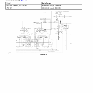
- Hydraulic Schematic
- Hydraulic Schematic
- Hydraulic Schematic
- Electrical Schematic (part 1 of 3)
- Electrical Schematic (part 2 of 3)
- Electrical Schematic (part 3 of 3)
- Wire Harness Drawing – Frame
- Wire Harness Diagram – Frame
- Wire Harness Drawing – Platform
- Wire Harness Diagram – Platform
- Wire Harness Diagram – Platform (continued)
- Wire Harness Drawing – Engine
- Wire Harness Diagram – Engine
- Wire Harness – Headlights
- Wire Harness – Cab Rooftop
- Wire Harness – Cab Control Panel
- Wire Harness – Cab Heat, Air Conditioning
- Wire Harness – InchMode (optional)
- Wire Harness – Loader Selector Control Valve (SCV) Switch (optional)
- Wire Harness – Loader Selector Control Valve (SCV) Valve (optional)
- Wire Harness – Rear Selector Control Valve (SCV) Kit (optional)
- Wire Harness – Cab Work Light Kit (optional)
- Wire Harness – Domestic Road Light Kit (optional)
- Wire Harness – Turn Signal, Hazard Lights (optional)
- Wire Harness – International Road Light Kit (optional)
Be the first to review “Toro Outcross 9060 Service Repair Manual”
You must be logged in to post a review.

Reviews
There are no reviews yet.