
Toro Multi Pro 5800 (S.N 316000001 & up) Service Repair Manual
$34.00
Manual Included:
- Service Repair Manual: 527 Pages
Specifications:
- Brand: Toro
- Model: Multi Pro 5800 (S.N 316000001 & up)
- Type: Vehicles
- Manuals: Service Repair Manual
- Publication Numbers: 16232SL
- Language: English
- Format: PDF
- Description
- Reviews (0)
Description
Table of Content – Multi Pro 5800 (S.N 316000001 & up)
- Title Page
- Revision History
- Reader Comments
- Preface
- Table Of Contents
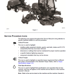
- 1 – Safety
- Safety Instructions
- Before Operating
- While Operating
- Maintenance and Service
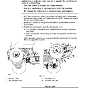
- Jacking Instructions
- Safety and Instruction Decals
- 2 – Product Records and Maintenance
- Product Records
- Maintenance
- Equivalents and Conversions
- Torque Specifications
- Fastener Identification
- Using a Torque Wrench with an Offset Wrench
- Standard Torque for Dry, Zinc Plated and Steel Fasteners (Inch Series Fasteners)
- Standard Torque for Dry, Zinc Plated and Steel Fasteners (Metric Fasteners)
- Other Torque Specifications
- Conversion Factors
- 3 – Kubota Diesel Engine
- Specifications
- General Information
- Operator's Manual
- Kubota Workshop Manual
- Adjustments
- Adjust Throttle Cable
- Service and Repairs
- Fuel System
- Air Cleaner
- Exhaust System
- Radiator
- Engine
- Flywheel Coupler
- KUBOTA WORKSHOP MANUAL, DIESEL ENGINE, 05−E3B SERIES
- 4 – Kubota Gasoline Engine
- Specifications
- General Information
- Operator's Manual
- Kubota Workshop and Troubleshooting Manuals
- Kubota Gasoline Engine
- Kubota Gasoline Engine Electronic Control Module (ECM)
- Service and Repairs
- Fuel Tank
- Evaporative Control System (machine serial numbers above 405700000)
- Air Cleaner
- Exhaust System
- Radiator
- Engine
- Flywheel Coupler
- KUBOTA WORKSHOP MANUAL,GASOLINE ENGINE WG1605−G−E3
- KUBOTA DIAGNOSIS MANUAL − ECM SYSTEM,GASOLINE ENGINE WG1605−G−E3
- 5 – Hydraulic System
- Specifications
- General Information
- Operator's Manual
- Traction Circuit Component Failure
- Hydraulic Hoses
- Hydraulic Hose and Tube Installation (O-Ring Face Seal Fitting)
- Hydraulic Fitting Installation (SAE Straight Thread O-Ring Fitting into Component Port)
- Hydraulic Schematics
- Hydraulic Flow Circuits
- Traction Circuit
- Steering Circuit (serial numbers below 405700000)
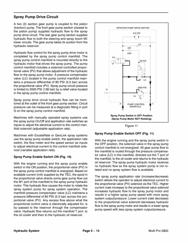
- Spray Pump Drive Circuit
- Spray Boom Lift Circuit
- Special Tools
- Hydraulic Pressure Test Kit
- 15 GPM Hydraulic Tester Kit (Pressure and Flow)
- 40 GPM Hydraulic Tester (Pressure and Flow)
- Hydraulic Hose Kit
- High Flow Hydraulic Filter Kit
- O-Ring Kit
- Hydraulic Test Fitting Kit
- Remote Starter Switch
- Troubleshooting
- Testing
- Traction Circuit – Charge Pressure Test
- Traction Circuit – Charge Pump Flow Test
- Traction Circuit – Wheel Motor Efficiency Test
- Traction Circuit – Traction (Piston) Pump Flow and Relief Pressure Test
- Steering, Boom Lift Circuit – Gear Pump P2 Flow and Circuit Relief Pressure Test (Using Tester with Flow Meter and Pressure…
- Steering, Boom Lift Circuit – Steering Control Valve and Steering Cylinder Test
- Steering, Boom Lift Circuit – Boom Lift Cylinder Internal Leakage Test
- Spray Pump Circuit – Gear Pump P1 Flow Test (Using Tester with Flow Meter and Pressure Gauge)
- Adjustments
- Adjust Traction Pedal for Neutral
- Service and Repairs
- General Precautions for Removing and Installing Hydraulic System Components
- Check Hydraulic Lines and Hoses
- Priming Hydraulic Pumps
- Flush Hydraulic System
- Filtering Closed−Loop Traction Circuit
- Charging Hydraulic System
- Gear Pump
- Gear Pump Service
- Traction (Piston) Pump
- Traction (Piston) Pump Service
- Wheel Motors
- Wheel Motor Service
- Spray Pump Drive Motor and Control Manifold Assembly
- Spray Pump Drive Motor Service
- Spray Pump Control Manifold Service
- Steering Control Valve
- Steering Control Valve Service
- Steering Cylinder
- Steering Cylinder Service
- Boom Lift Manifold
- Boom Lift Manifold Service
- Boom Lift Cylinders
- Boom Lift Cylinder Service
- Oil Cooler
- Hydraulic Reservoir
- Electrohydraulic In-line (EHi) Steering Valve (Optional AutoSteer Kit)
- Electrohydraulic In-line (EHI) Steering Valve Service (Optional AutoSteer Kit)
- EATON MODEL 72400 SERVO CONTROLLEDPISTON PUMP REPAIR INFORMATION
- EATON MODEL 74318 and 74348 PISTON MOTORS: FIXED DISPLACEMENT, VALVE PLATE DESIGN REPAIR INFORMATION
- PARKER TORQLINK SERVICE PROCEDURE
- DANFOSS STEERING UNIT TYPE OSPM SERVICEMANUAL
- DANFOSS EHi STEERING VALVE Service Repair Manual
- 6 – Electrical System
- General Information
- Operator's Manual
- Toro Electronic Controller (TEC)
- Kubota Gasoline Engine Electronic Control Unit (ECU)
- Kubota Engine Electrical Components
- CAN-bus Communications
- Electrical Drawings
- Special Tools
- Multimeter
- Dielectric Gel
- Terminal Protector
- Battery Hydrometer
- Traction Speed Sensor Test Harness
- Flow Meter Sensor Test Harness
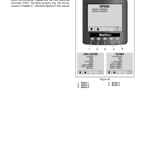
- InfoCenter Display
- InfoCenter Display ScreensExcelaRate Spray System
- InfoCenter Display ScreensGeoLink Spray System
- Splash Screen
- Operator's Information
- Spray Areas
- Main Menu
- Set Rates
- Settings
- Calibration
- Service
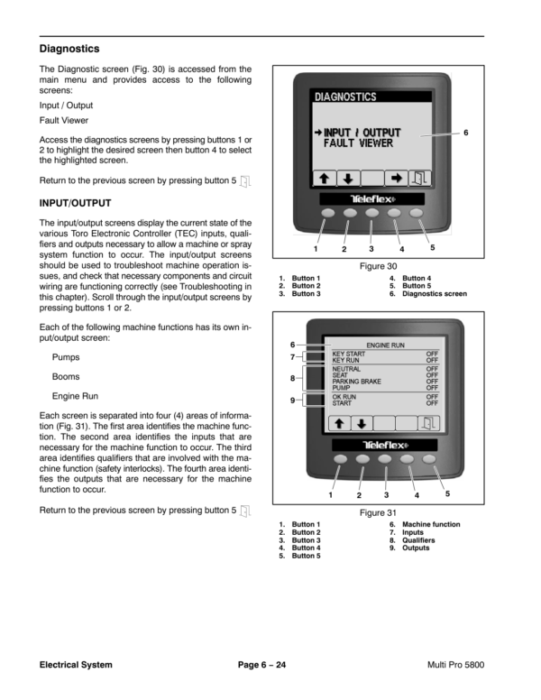
- Diagnostics
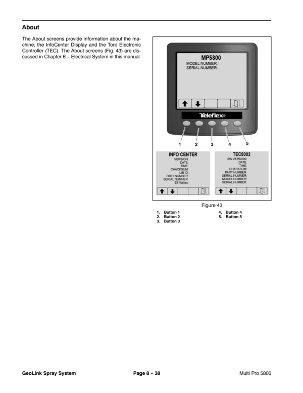
- About
- Troubleshooting
- Starting Problems
- General Operation Problems
- Operator Advisories
- Using the InfoCenter Display for Troubleshooting
- Machine Faults
- Engine Faults (Gasoline Engines Only)
- Electrical System Quick Checks
- Battery Test (Open Circuit Test)
- Charging System Test
- Glow Plug System Test (Diesel Engine Only)
- Check Operation of Interlock Switches
- Adjustments
- Brake Pedal Switch
- Steering Position Sensor (Optional AutoSteer)
- Component Testing
- Fusible Links
- Fuses
- Engine Fuses (Gasoline Engines Only)
- Toro Electronic Controller (TEC)
- PVED-CLS Controller (Optional AutoSteer)
- Ignition Switch
- Indicator Lights (Diesel Engines Only)
- Headlight Switch (Standard)
- Spray-Mode Switch (ExcelaRate Spray Systems Only)
- Application-Rate Switch (machines without GeoLink Spray System)
- Road Switch (Optional AutoSteer)
- Speed-Lock Switch
- Boom Lift Switches
- Spray Pump Enable and Agitation Switches
- Master Boom (Spray Enable) Switch
- Remote Engage Switch (Optional AutoSteer)
- Boom Control Switches
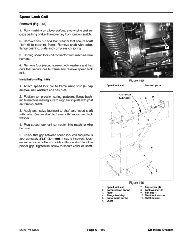
- Speed Lock Coil
- Brake Pedal Switch
- Relays with Four (4) Terminals
- Relays with Five (5) Terminals
- Engine Relays (Gasoline Engines Only)
- Traction Speed Sensor
- Hydraulic Valve Solenoid Coils
- Neutral Switch
- Fuel Run, Stop Solenoid (Diesel Engines Only)
- Glow Plug Controller (Diesel Engines Only)
- Fuel Pump (Gasoline Engines Only)
- Fuel Pump (Diesel Engines Only)
- Fuel Level Sender (Gasoline Engines Only)
- Fuel Level Sender (Diesel Engines Only)
- Coolant Temperature Sender
- Oil Pressure Switch
- CAN-bus Terminator Resistors
- Diode Assemblies
- Resistor Assemblies
- Spray System Valve Actuators
- Operator Seat Switch
- Audible Alarm
- Throttle Assembly (Gasoline Engines Only)
- Flow Meter Sensor
- Pressure Transducer
- Horn Button (Optional)
- Tank Clean Rinse Pump Switch (Optional)
- Foam Marker ON, OFF Switch (Optional)
- Foam Marker Control Switch (Optional)
- Electric Hose Reel Motor Switch (Optional)
- Electric Hose Reel Rate Switch (Optional)
- Road Headlight Switch (Optional)
- Hazard Light Switch (Optional)
- Service and Repairs
- Headlights
- Traction Speed Sensor
- Flow Meter Sensor
- Speed Lock Coil
- Battery Storage
- Battery Care
- Battery Service
- 7 – ExcelaRate Spray System
- Specifications
- General Information
- User Manuals
- Precautions Concerning Chemicals Used in Spray System
- Precautions for Removing or Adjusting Spray System Components
- Special Tools
- Quick Check Catch Jug – 64 oz (946 ml)
- ExcelaRate Spray System Diagram
- ExcelaRate Spray System Operation
- InfoCenter Display
- InfoCenter Display ScreensExcelaRate Spray System
- Splash Screen
- Operator's Information
- Spray Areas
- Main Menu
- Set Rates
- Settings
- Calibration
- Service
- Diagnostics
- About
- Troubleshooting
- Spray System Problems
- Operator Advisories
- Using the InfoCenter Display for Troubleshooting
- Machine Faults
- Service and Repairs
- Spray System Components
- Spray Pump
- Spray Pump Service
- Pressure Relief Valve
- Spray Control Manifold Assembly
- Agitation Valve Assembly
- Boom Section Valve Assembly
- Boom Section Valve and Agitation Valve Service
- Agitation Bypass Valve Service
- Boom Section Bypass Valve Service
- Boom Section Bypass Shut-Off Valve and Agitation Throttle Valve Service
- Flow Meter
- Flow Meter Service
- Suction Line
- Agitation Line
- Drain Line
- Turret Bodies
- Turret Body Service
- Nozzle Flow Meter (Optional NozzAlert Nozzle Sensing System)
- Spray Boom Hinge
- Spray Tank
- 8 – GeoLink Spray System
- Calibrating the AutoSteer Steering System Components (Optional) 56
- Specifications
- General Information
- User Manuals
- GeoLink Spray System Service and Support
- Precautions Concerning Chemicals Used in Spray System
- Precautions for Removing or Adjusting Spray System Components
- GeoLink Terminology
- Special Tools
- Quick Check Catch Jug – 64 oz (946 ml)
- GeoLink Spray System Diagram
- GeoLink Spray System Operation
- GeoLink Components
- X25 and X30 Control Console Screens
- Operation Screen
- Setup Screen
- InfoCenter Display
- InfoCenter Display ScreensGeoLink Spray System
- Splash Screen
- Operator's Information
- Main Menu
- Settings
- Service
- Diagnostics
- About
- Troubleshooting
- Automatic Section Control Override
- Remote Assistance (X30 Consoles Only)
- X25 or X30 Control Console Error Messages
- Crash Reports
- Guidance and Rate Management System
- Operator Advisories (InfoCenter Display)
- Using the InfoCenter Display for Troubleshooting
- Machine Faults (InfoCenter Display)
- AutoSteer Faults (Optional AutoSteer Only)
- Product Handling System
- Adjustments
- Compass Calibration
- Flow Meter Calibration
- Calibrating the AutoSteer Steering System Components (Optional)
- Service and Repairs
- GPS Antenna (AGI-4)
- Modem (machines with RTK correction)
- Inertial Measurement Unit (IMU) (machines with RTK correction)
- Automatic Section Controller (ASC-10)
- X25 or X30 Control Console
- CAN-bus Terminator Resistors
- Fuses
- Material Handling “Wet” Components
- Spray Pump
- Spray Pump Service
- Pressure Relief Valve
- Spray Control Manifold Assembly
- Agitation Valve Assembly
- Nozzle Valve Assembly
- Nozzle Valve and Agitation Valve Service
- Agitation Bypass Valve Service
- Agitation Throttle Valve Service
- Flow Meter
- Flow Meter Service
- Suction Line
- Agitation Line
- Drain Line
- Turret Bodies
- Turret Body Service
- Nozzle Flow Meter (Optional NozzAlert Nozzle Sensing System)
- Spray Boom Hinge
- Spray Tank
- 9 – Chassis
- Specifications
- General Information
- Operator's Manual
- Adjustments
- Planetary Drive Assembly Endplay (OPH-2 series planetary drives)
- Service and Repairs
- Undercarriage Shrouds
- Wheel Assemblies
- Tie Rod
- Front Wheel Hubs
- Front Spindles
- Front Suspension
- Planetary Drive Assembly
- OPH-2 Series Planetary Drive Service
- VA02 Series Planetary Drive Service
- Brake Cables
- Brake Assembly
- Brake Inspection and Repair
- Seats
- Console Assembly
- 10 – Ultra Sonic Boom Kit (Optional)
- General Information
- Installation Instructions
- Parts Catalog
- System Configuration
- CAN-bus Communications
- Precautions Concerning Chemicals Used in Spray System
- Precautions for Removing or Adjusting Spray System Components
- Hydraulic Schematic
- Electrical Schematic
- Ultra Sonic Boom System Operation
- Sprayer Operation on Level Turf
- Downward Slope in Turf Encountered
- Rise in Turf Encountered
- Boom Level Changed by Operator During Automatic Operation
- Manual Boom Operation
- Troubleshooting
- Ultra Sonic Boom Light
- Ultra Sonic Boom Calibration
- Troubleshooting Chart
- Service and Repairs
- Ultra Sonic Boom Fuses
- Ultra Sonic Boom Switch
- Sonic Sensors
- Toro Electronic Controller (TEC)
- CAN-bus Termination Resistors
- Ultra Sonic Boom Lift Manifold Service
- Appendix A: Foldout Drawings
- Electrical Drawing Designations
- Hydraulic Schematic – Multi Pro 5800 (serial numbers 316000000 to 400699413)
- Hydraulic Schematic – Multi Pro 5800 (serial numbers 400966414 to 405699999)
- Hydraulic Schematic – Multi Pro 5800 (serial numbers above 405700000)
- Hydraulic Schematic – Multi Pro 5800 (serial numbers above 405700000) with AutoSteer (Optional)
- Electrical Schematic – Multi Pro 5800-D (serial numbers 316000000 to 403460000)
- Electrical Schematic – Multi Pro 5800-D (serial numbers 316000000 to 403460000)
- Electrical Schematic – Multi Pro 5800-D (serial numbers above 40346000)
- Electrical Schematic – Multi Pro 5800-D (serial numbers above 40346000)
- Electrical Schematic – Multi Pro 5800-G (serial numbers 316000000 to 403460000)
- Electrical Schematic – Multi Pro 5800-G (serial numbers 316000000 to 403460000)
- Electrical Schematic – Multi Pro 5800-G (serial numbers above 40346000)
- Electrical Schematic – Multi Pro 5800-G (serial numbers above 40346000)
- Electrical Schematic – Multi Pro 5800 (serial numbers above 316000000) with GeoLink Spray System (Optional)
- Electrical Schematic – Ultra Sonic Boom Kit (Optional)
- Front Wire Harness Drawing – Multi Pro 5800-D (serial numbers 316000000 to 403460000)
- Front Wire Harness Diagram – Multi Pro 5800-D (serial numbers 316000000 to 403460000)
- Front Wire Harness Diagram – Multi Pro 5800-D (serial numbers 316000000 to 403460000)
- Front Wire Harness Drawing – Multi Pro 5800-D (serial numbers above 403460000)
- Front Wire Harness Diagram – Multi Pro 5800-D (serial numbers above 403460000)
- Front Wire Harness Diagram – Multi Pro 5800-D (serial numbers above 403460000)
- Front Wire Harness Drawing – Multi Pro 5800-G (serial numbers 316000000 to 403445000)
- Front Wire Harness Diagram – Multi Pro 5800-G (serial numbers 316000000 to 403445000)
- Front Wire Harness Diagram – Multi Pro 5800-G (serial numbers 316000000 to 403445000)
- Front Wire Harness Drawing – Multi Pro 5800-G (serial numbers above 403445000)
- Front Wire Harness Diagram – Multi Pro 5800-G (serial numbers above 403445000)
- Front Wire Harness Diagram – Multi Pro 5800-G (serial numbers above 403445000)
- Rear Wire Harness Drawing – Multi Pro 5800 (serial numbers above 316000000)
- Rear Wire Harness Diagram – Multi Pro 5800 (serial numbers above 316000000)
- Rear Wire Harness Drawing – Multi Pro 5800 (serial numbers above 316000000) with GeoLink Spray System (Optional)
- Rear Wire Harness Diagram – Multi Pro 5800 (serial numbers above 316000000) with GeoLink Spray System (Optional)
- Wire Harness Drawing – AutoSteer Kit (Optional)
- Wire Harness Diagram – AutoSteer Kit (Optional)
- Wire Harness Drawing – Ultra Sonic Boom Kit (Optional)
- Wire Harness Diagram – Ultra Sonic Boom Kit (Optional)
- Main Wire Harness – NozzAlert Nozzle Sensing System (Optional)
- Center Section Wire Harness – NozzAlert Nozzle Sensing System (Optional)
- Right Boom Wire Harness – NozzAlert Nozzle Sensing System (Optional)
- Left Boom Wire Harness – NozzAlert Nozzle Sensing System (Optional)
Be the first to review “Toro Multi Pro 5800 (S.N 316000001 & up) Service Repair Manual”
You must be logged in to post a review.


Reviews
There are no reviews yet.