
Toro Reelmaster 5410, 5510, 5610 Service Repair Manual
$34.00
Manual Included:
- Service Repair Manual: 674 Pages
Specifications:
- Brand: Toro
- Model: Reelmaster 5410, 5510, 5610
- Type: Large Reel Mowers
- Manuals: Service Repair Manual
- Publication Numbers: 15216SL
- Language: English
- Format: PDF
- Description
- Reviews (0)
Description
Table of Content – Reelmaster 5410, 5510, 5610
- Title Page
- Revision History
- Reader Comments
- NOTES:
- Preface
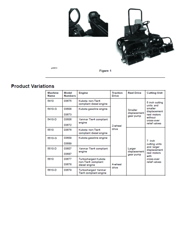
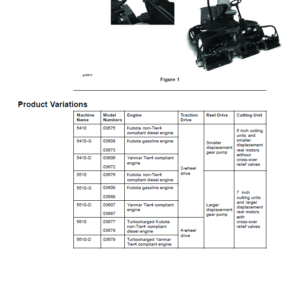
- Product Variations
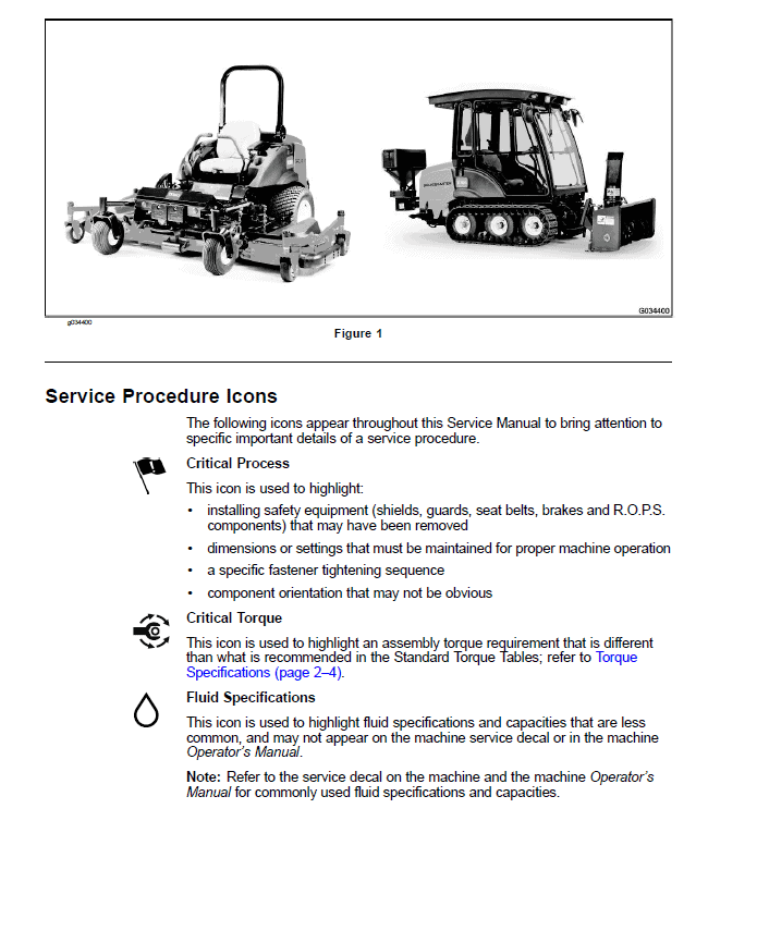
- Service Procedure Icons
- Table of Contents
- Chapter 1 : Safety
- Safety Instructions
- Supervisor’s Responsibilities
- Before Operating the Machine
- While Operating the Machine
- Maintenance and Service
- Jacking Instructions
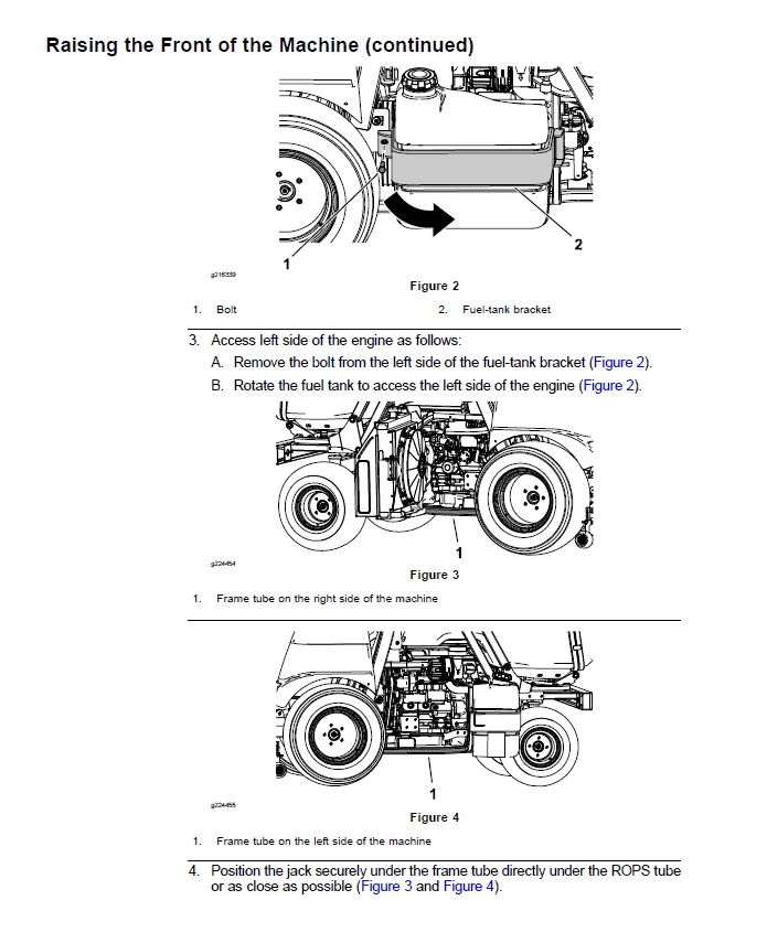
- Raising the Front of the Machine
- Raising the Rear of the Machine
- Safety and Instructional Decals
- Chapter 2 : Specifications and Maintenance
- Specifications
- Decimal and Millimeter Equivalents
- U.S. to Metric Conversions
- Torque Specifications
- Identifying the Fastener
- Fasteners with a Locking Feature
- Calculating the Torque Values When Using a Drive-Adapter Wrench
- Standard Torque for Dry, Zinc Plated, and Steel Fasteners (Inch Series)
- Standard Torque for Dry, Zinc Plated, and Steel Fasteners (Metric Fasteners)
- Other Torque Specifications
- Conversion Factors
- Shop Supplies
- Special Tools
- Chapter 3 : Kubota Diesel Engine
- 1 Specifications
- Kubota Diesel Engine
- General Information
- Operator’s Manuals
- Kubota Workshop Manual
- Shutting off the Engine (Reelmaster 5610)
- Adjustments
- Adjusting the Throttle Control
- Service and Repairs
- Air Cleaner Assembly
- Exhaust System
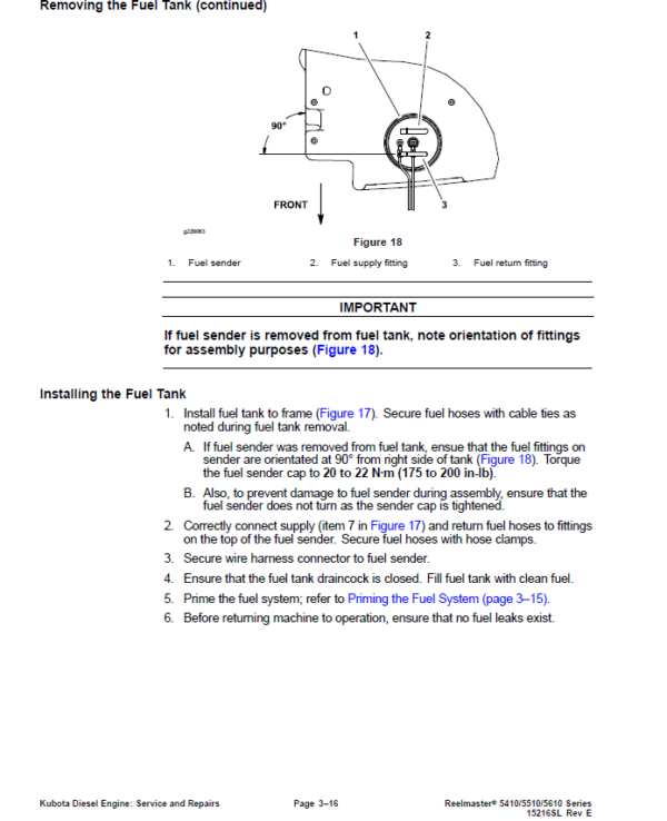
- Fuel System
- Radiator Assembly
- Engine
- Kubota Workshop Manual, Diesel Engine, 05-E3B Series
- Chapter 4 : Yanmar Diesel Engine
- 1 Specifications
- Yanmar Diesel Engine
- General Information
- Traction Unit Operator’s Manual
- Yanmar Engine Service and Troubleshooting Manuals
- Engine Electronic Control Unit (ECU)
- Yanmar Engine
- Diesel Particulate Filter (DPF)
- Shutting Off the Engine (Reelmaster 5610-D)
- Service and Repairs
- Air Cleaner System
- Exhaust System
- Radiator
- Fuel System
- Engine
- Yanmar TNV (Tier 4) Series Service Repair Manual
- Yanmar TNV (Tier 4) Series Troubleshooting Manual
- Chapter 5 : Kubota Gasoline Engine
- 1 Specifications
- Kubota Gasoline Engine
- General Information
- Traction Unit Operator’s Manual
- Kubota Workshop and Diagnosis Manuals
- Kubota Gasoline Engine
- Engine Electronic Control Unit (ECU)
- Service and Repairs
- Air Cleaner Assembly
- Exhaust System
- Fuel System
- Fuel Evaporative Control System
- Radiator and Oil Cooler Assembly
- Engine
- Kubota Workshop Manual, WG1605-G-E3
- Kubota Diagnosis Manual, ECM System, WG1605-G-E3
- Chapter 6 : Hydraulic System
- 1 Specifications
- Hydraulic System
- General Information
- Checking the Hydraulic Fluid
- Pushing or Towing the Traction Unit
- Releasing Pressure from the Hydraulic System
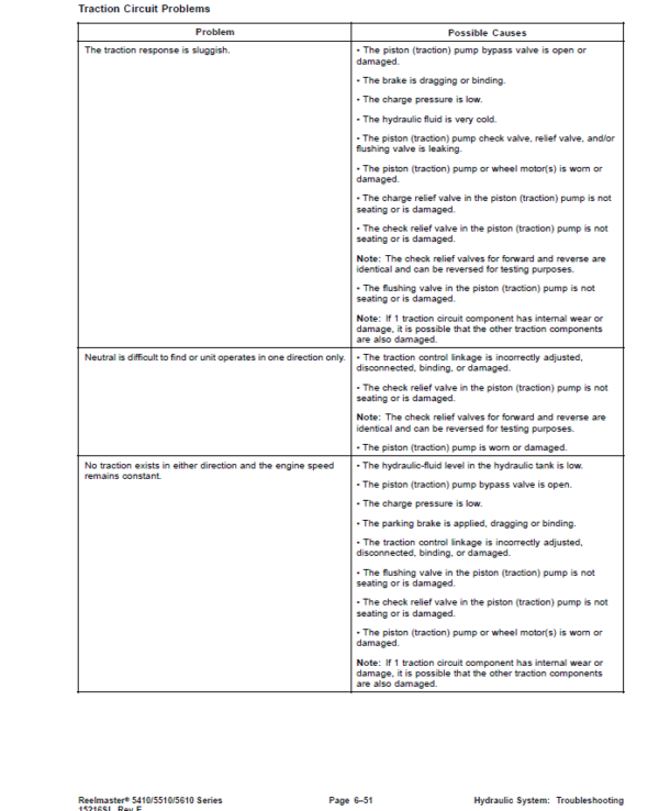
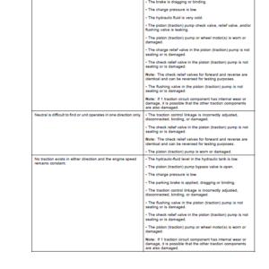
- Traction Circuit Component Failure
- Hydraulic Hoses
- Installing the Hydraulic Hose and Tube (O-Ring Face Seal Fitting)
- Installing the Hydraulic Fittings (SAE Straight Thread O-Ring Fitting into the Component Port)
- Hydraulic Schematics
- Hydraulic Flow Diagrams (5410, 5410-D, 5510, 5510-D, 5610)
- Traction Circuit (5410, 5410-D, 5510, 5510-D, 5610)
- Mow Circuit (5410, 5410-D, 5510, 5510-D, 5610)
- Lift Circuit (5410, 5410-D, 5510, 5510-D, 5610)
- Steering Circuit (5410, 5410-D, 5510, 5510-D, 5610)
- Hydraulic Flow Diagrams (5610-D)
- Traction Circuit (5610-D)
- Mow Circuit (5610-D)
- Lift Circuit (5610-D)
- Steering Circuit (5610-D)
- Special Tools
- Hydraulic Pressure Testing Kit
- 15 GPM Hydraulic Tester Kit (Pressure and Flow)
- 40 GPM Hydraulic Tester (Pressure and Flow)
- Hydraulic Hose Kit
- O-Ring Kit
- Hydraulic Test Fitting Kit
- High Flow Hydraulic Filter Kit
- Spindle Plug
- Wheel Hub Puller
- Measuring Container
- Remote Starter Switch
- Troubleshooting
- Testing the Hydraulic System
- Traction Circuit Relief Valve (R3) and (R4) Pressure Test (5410, 5410-G, 5410-D, 5510, 5510-G, 5510-D, 5610)
- Traction Circuit Charge Pressure Test (5410, 5410-G, 5410-D, 5510, 5510-G, 5510-D, 5610)
- Gear Pump (P3) Flow Test (Using Tester with Flow Meter and Pressure Gauge) (5410, 5410-G, 5410-D, 5510, 5510-G, 5510-D, 5610)
- Front Wheel Motor Efficiency Test (5410, 5410-G, 5410-D, 5510, 5510-G, 5510-D, 5610)
- Piston (Traction) Pump Flow Test (Using Tester with Flow Meter and Pressure Gauge) (5410, 5410-G, 5410-D, 5510, 5510-G, 5510-D, 5610)
- Relief Valve (R1) and (R2) Pressure Test (Cutting (Mow) Circuit) (5410, 5410-G, 5410-D, 5510, 5510-G, 5510-D, 5610)
- Gear Pump (P1) and (P2) Flow Test (Using Tester with Flow Meter and Pressure Gauge) (5410, 5410-G, 5410-D, 5510, 5510-G, 5510-D, 5610)
- Cutting Reel Motor Efficiency Test (Using Tester with Flow Meter and Pressure Gauge) (5410, 5410-G, 5410-D, 5510, 5510-G, 5510-D, 5610)
- Cutting Reel Motor Cross-Over Relief Pressure Test (5510, 5510-G, 5510-D, 5610)
- Lift Relief Valve (SVRV) Pressure Test (5410, 5410-G, 5410-D, 5510, 5510-G, 5510-D, 5610)
- Gear Pump (P4) Flow Test (Using Tester with Flow Meter and Pressure Gauge) (5410, 5410-G, 5410-D, 5510, 5510-G, 5510-D, 5610)
- Lift Cylinder Internal Leakage Test (5410, 5410-G, 5410-D, 5510, 5510-G, 5510-D, 5610)
- Steering Relief Valve (R10) Pressure Test (5410, 5410-G, 5410-D, 5510, 5510-G, 5510-D, 5610)
- Steering Cylinder Internal Leakage Test (5410, 5410-G, 5410-D, 5510, 5510-G, 5510-D, 5610)
- Testing the Traction Circuit–Charge Pressure (5610-D)
- Testing the Traction Circuit–Wheel Motor Efficiency (5610-D)
- Testing the Traction Circuit–Piston Pump, Hydrostat Flow and Relief Pressure (5610-D)
- Testing the Mow Circuit–Circuit Pressure (5610-D)
- Testing the Mow Circuit–Reel Motor Efficiency, Case Drain (5610-D)
- Testing the Mow Circuit–Reel Motor Cross−Over Relief Pressure (5610-D)
- Testing the Mow Circuit–Relief Valve (RV1) and (RV2) Pressure (5610-D)
- Testing the Mow Circuit–Gear Pump (P1) and (P2) Flow (5610-D)
- Testing the Steering Circuit–Steering Control Valve, Relief Valve (R10) Pressure, and Steering Cylinder (5610-D)
- Testing the Steering Circuit–Gear Pump (P3) Flow (5610-D)
- Testing the lift Circuit–Relief Valve (SVRV) Pressure (5610-D)
- Testing the Lift Circuit–Lift Cylinder Internal Leakage (5610-D)
- Testing the Lift Circuit–Gear Pump (P4) Flow (5610-D)
- Service and Repairs
- General Precautions for Removing and Installing the Hydraulic System Components
- Checking the Hydraulic Lines and Hoses
- Priming the Hydraulic Pumps
- Flushing the Hydraulic System
- Filtering the Closed-Loop Traction Circuit
- Charging the Hydraulic System
- Hydraulic Tank
- Piston (Traction) Pump Control Assembly
- Hydraulic Pump Driveshaft
- Hydraulic Pump Assembly
- Servicing the Piston (Traction) Pump
- Servicing the Gear Pump
- Front Wheel Motors
- Servicing the Front Wheel Motor
- Rear Wheel Motors (Machine with CrossTrax AWD)
- Servicing the Rear Wheel Motor (Machine with CrossTrax AWD)
- CrossTrax™ AWD Control Manifold Assembly
- Servicing the CrossTrax AWD Control Manifold Assembly
- Mow Control Manifold Assembly
- Servicing the Mow Control Manifold Assembly
- Lift Control Manifold
- Servicing the Lift Control Manifold
- Servicing a Control Manifold Cartridge Valve
- Cutting Reel Motor
- Servicing the Cutting Reel Motor (Casappa)
- Servicing the Cutting Reel Motor (Sauer-Danfoss)
- Lift Cylinder
- Servicing the Lift Cylinder
- Steering Control Valve
- Servicing the Steering Control Valve
- Steering Cylinder
- Servicing the Steering Cylinder
- Oil Cooler (5410, 5510, 5610)
- Radiator and Oil Cooler Assembly (5410-G, 5410-D, 5510-G, 5510-D, 5610-D)
- Danfoss LPV Closed Circuit Axial Piston Pump Service Repair Manual
- Eaton Delta Motors Parts and Repair Manual
- Parker Torqmotor Service Procedure (TC, TB, TE, TJ, TF, TG, TH, and TL Series)
- Danfoss Steering Unit Type OSPM Service Repair Manual
- Chapter 7 : Electrical System
- General Information
- Electrical Schematic and Wire Harness Drawings, Diagrams
- Toro Electronic Controller (TEC)
- CAN-bus Communications
- Yanmar Engine Electronic Control Unit (ECU)
- Yanmar Engine Electrical Components
- Kubota Gasoline Engine Electronic Control Unit (ECU)
- Kubota Gasoline Engine Electrical Components
- Special Tools
- Multimeter
- Terminal Protector
- Battery Hydrometer
- Dielectric Gel
- InfoCenter Display
- Splash Screen
- Main Information Screen
- Operator Advisory Screen
- Main Menu Screen
- Faults Screen
- Service Screen
- Diagnostics Screen
- Settings Screen
- About Screen
- Troubleshooting
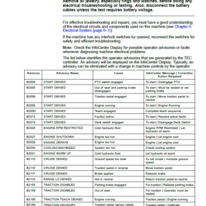
- Operator Advisories
- Using the InfoCenter Display for Troubleshooting
- Machine Faults
- Engine Faults
- General Run and Transport Problems
- Electrical System Quick Checks
- Testing the Battery (Open Circuit Test)
- Testing the Charging System
- Testing the Glow Plug System (Machines with Kubota Diesel Engine)
- Checking the Operation of the Interlock Switches
- Adjustments
- Traction Neutral Switch
- Parking Brake Switch
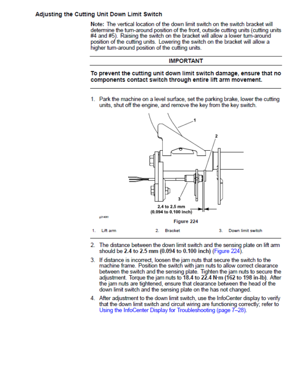
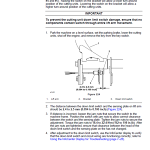
- Cutting Unit Down Limit Switch
- Mow, Transport Switch
- Testing the Electrical Components
- Fusible Link Harness (Machines with Kubota or Yanmar Diesel Engine)
- System Fuses
- Engine Fuses (Gasoline Engine)
- Toro Electronic Controller (TEC)
- Key Switch
- Reel Engage Switch
- Engine Speed Switch (If Equipped)
- Lower, Raise Joystick Switches
- Headlight Switch
- Seat Switch
- Cutting Unit Down Limit Switch
- Traction Neutral Switch
- Parking Brake Switch
- Mow, Transport Switch
- Backlap Switches
- Oil Pressure Switch (Machine with Kubota Engine)
- Relays with 4 Terminals
- Relays with 5 Terminals (Diesel Engine)
- Engine Relays with 5 Terminals (Gasoline Engine)
- Hydraulic Solenoid Valve Coils
- Temperature Sender (Machine with Kubota Diesel Engine)
- Engine Run Solenoid (Machine with Kubota Diesel Engine)
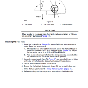
- Fuel Sender (Diesel Engine)
- Fuel Sender (Gasoline Engine)
- Fuel Pump (Machine with Yanmar Diesel Engine)
- Fuel Pump (Machine with Kubota Diesel Engine)
- Fuel Pump (Machine with Kubota Gasoline Engine)
- CAN-bus Terminator Resistor
- Resistor Assembly (Machine with Yanmar Diesel or Kubota Gasoline Engine)
- Diode Assemblies (Diesel Engine)
- Service and Repairs
- Hydraulic Solenoid Valve Coils
- Backlap Switches
- Battery Storage
- Battery Care
- Servicing the Battery
- Chapter 8 : Chassis
- 1 Specifications
- Chassis
- General Information
- Special Tools
- Wheel Hub Puller
- Service and Repairs
- Wheels
- Steering Column
- Servicing the Brakes
- Rear Wheel Bearings (Machines with 2-Wheel Drive)
- Rear Axle Motor Housings
- Rear Axle
- Control Arm
- Operator Seat
- Mechanical Seat Suspension
- Front Lift Arms
- Rear Lift Arms
- Hood
- Chapter 9 : Cutting Unit
- 1 Specifications
- Cutting Unit Specifications
- General Information
- Special Tools
- Aftercut Appearance
- Adjustments
- Characteristics
- Adjusting the Reel Bearing (cutting units with painted side plates)
- Leveling the Rear Roller
- Service and Repairs
- Hydraulic Reel Motor
- Backlapping
- Bedbar Assembly
- Bedknife Replacement and Grinding
- Servicing the Bedbar Adjuster
- Reel Assembly (cutting units with painted side plates)
- Reel Assembly Service (cutting units with painted side plates)
- Reel Assembly (cutting units with aluminum side plates)
- Reel Assembly Service (cutting units with aluminum side plates)
- Preparing the Reel for Grinding
- Front Roller
- Rear Roller
- Servicing the Roller
- Rear Roller Brush – Optional (cutting units with painted side plates)
- Rear Roller Brush – Optional (cutting units with aluminum side plates)
- Chapter 10 : Belt Driven Groomer (Optional)
- General Information
- Grooming Performance
- Groomer Reel Mechanical Problems
- Adjustments
- Adjusting the Height, Depth of the Groomer
- Service and Repairs
- Replacing the Groomer Drive Belt
- Groomer Plate Assembly
- Groomer Reel
- Servicing the Groomer Reel
- Groomer Pivot Hub
- Height Adjuster Assembly
- Servicing the Grooming Brush (Optional)
- Chapter 11 : Universal Groomer (Optional)
- General Information
- Factors Affecting Grooming
- Troubleshooting
- Groomer Reel Mechanical Problems
- Service and Repairs
- Gear Box Assembly
- Idler Assembly
- Groomer Reel
- Servicing the Groomer Reel
- Height Adjuster Assembly
- Servicing the Grooming Brush (Optional)
- Appendix A: Foldout Drawings
- Electrical Drawing Designations
- Hydraulic Schematic-5410, 5410-D
- Hydraulic Schematic-5510, 5510-D, 5610
- Hydraulic Schematic-5610-D
- Electrical Schematic-5410, 5510, 5610 (Models with Kubota Diesel Engine) (Serial Numbers Below 403430000)
- Electrical Schematic-5410, 5510, 5610 (Models with Kubota Diesel Engine) (Serial Numbers Above 403430000)
- Electrical Schematic-5410-D, 5510-D, 5610-D (Models with Yanmar Diesel Engine) (Serial Numbers Below 403430000)
- Electrical Schematic-5410-D, 5510-D, 5610-D (Models with Yanmar Diesel Engine) (Serial Numbers Above 403430000)
- NO TITLE
- Electrical Schematic-5410-G, 5510-G (Models with Kubota Gasoline Engine)
- Wire Harness Drawing-Main (Serial Number Below 403430000)
- Wire Harness Drawing-Main (Serial Number Below 403430000)
- Wire Harness Drawing-Main (Serial Numbers 403430001 to 405680000)
- Wire Harness Drawing-Main (Serial Numbers 403430001 to 405680000)
- Wire Harness Drawing-Main (Serial Numbers Above 405680001)
- Wire Harness Drawing-Main (Serial Numbers Above 405680001)
- Wire Harness Drawing-Seat
- Wire Harness Drawing-Seat
- Engine Wire Harness Drawing-5410, 5510, 5610 (Models with Kubota Diesel Engine)
- Engine Wire Harness Diagram-5410, 5510, 5610 (Models with Kubota Diesel Engine)
- Engine Wire Harness Drawing-5410-D, 5510-D (Models 03672 and 03687 with Yanmar Diesel Engine)
- Engine Wire Harness Diagram-5410-D, 5510-D (Models 03672 and 03687 with Yanmar Diesel Engine)
- Engine Wire Harness Drawing-5410-D, 5510-D, 5610-D (Models 03606, 03607, and 03679)
- Engine Wire Harness Diagram-5410-D, 5510-D, 5610-D (Models 03606, 03607, and 03679)
- Engine Wire Harness Drawing-5410-G, 5510-G (Models with Kubota Gasoline Engine)
- Engine Wire Harness Diagram-5410-G, 5510-G (Models with Kubota Gasoline Engine)
Be the first to review “Toro Reelmaster 5410, 5510, 5610 Service Repair Manual”
You must be logged in to post a review.
Reviews
There are no reviews yet.