
Toro Reelmaster 5210, 5410, 5510, 5610 Series Service Repair Manual
$34.00
Manual Included:
- Service Repair Manual: 348 Pages
Specifications:
- Brand: Toro
- Model: Reelmaster 5210, 5410, 5510, 5610 Series
- Type: Large Reel Mowers
- Manuals: Service Repair Manual
- Publication Numbers: 06148SL
- Language: English
- Format: PDF
- Description
- Reviews (0)
Description
Table of Content – Reelmaster 5210, 5410, 5510, 5610 Series
- Title Page
- Revision History
- Reader Comments
- Preface
- Table Of Contents
- 1 – Safety
- Safety Instructions
- Before Operating
- While Operating
- Maintenance and Service
- Jacking Instructions
- Safety and Instruction Decals
- 2 – Product Records and Maintenance
- Product Records
- Maintenance
- Equivalents and Conversions
- Torque Specifications
- 3 – Kubota Diesel Engine
- General Information
- Traction Unit Operator’s Manual
- Stopping the Engine (Reelmaster 5610)
- Specifications: Reelmaster 5210
- Specifications: Reelmaster 5410 and 5510
- Specifications: Reelmaster 5610
- Adjustments
- Adjust Throttle Control
- Service and Repairs
- Fuel System
- Air Cleaner
- Exhaust System
- Radiator
- Engine
- Kubota 05 E2B Series Workshop Manual (S.N below 280000000)
- Kubota 05-E3B Series Workshop Manual (S.N 280000001 and up)
- 4 – Hydraulic System
- Specifications
- General Information
- Traction Unit Operator’s Manual
- Check Hydraulic Fluid
- Towing Traction Unit
- Hydraulic Hoses
- Hydraulic Fitting Installation
- Relieving Hydraulic System Pressure
- Traction Circuit Component Failure
- Hydraulic Schematics
- Hydraulic Flow Diagrams
- Traction Circuit
- Mow Circuit
- Lift Circuit – Raise Cutting Units
- Lift Circuit – Lower Cutting Units
- Steering Circuit
- Special Tools
- Troubleshooting
- General Hydraulic System Problems
- Traction Circuit Problems
- Mow Circuit Problems
- Lift Circuit Problems
- Steering Circuit Problems
- Testing
- Before Performing Hydraulic Tests
- Precautions for Hydraulic Testing
- Which Hydraulic Tests Are Necessary?
- Traction Circuit Relief Valve (R3) and (R4) Pressure Test
- Traction Circuit Charge Pressure Test
- Gear Pump (P3) Flow Test
- Front Wheel Motor Efficiency Test
- Piston (Traction) Pump Flow Test
- Relief Valve (R1) and (R2) Pressure Test
- Gear Pump (P1) and (P2) Flow Test
- Reel Drive Motor Efficiency Test
- Reel Drive Motor Cross–Over Relief Pressure Test
- Lift Relief Valve (SVRV) Pressure Test
- Gear Pump (P4) Flow Test
- Lift Cylinder Internal Leakage Test
- Steering Relief Valve (R10) Pressure Test
- Steering Cylinder Internal Leakage Test
- Service and Repairs
- General Precautions for Removing and Installing Hydraulic System Components
- Check Hydraulic Lines and Hoses
- Flush Hydraulic System
- Filtering Closed-Loop Traction Circuit
- Hydraulic System Start–up
- Hydraulic Reservoir
- Hydraulic Pump Drive Shaft
- Hydraulic Pump Assembly
- Piston (Traction) Pump Service
- Gear Pump Service
- Front Wheel Motor
- Wheel Motor Service (Parker)
- Front Wheel Motor Service (Eaton)
- Mow Control Manifold
- Mow Control Manifold Service
- Lift Control Manifold
- Lift Control Manifold Service
- CrossTrax AWD (Optional Kit) Manifold
- CrossTrax AWD (Optional Kit) Manifold Service
- Cutting Reel Motor
- Cutting Reel Motor Service (Bosch and Sauer-Danfoss)
- Cutting Reel Motor Service (Casappa)
- Lift Cylinder
- Lift Cylinder Service
- Steering Control Valve
- Steering Control Valve Service
- Steering Cylinder
- Steering Cylinder Service
- Oil Cooler
- Danfoss LPV Pump Repair Manual
- Danfoss LPV Pump Service Repair Manual
- Parker Torqmotor Service Procedure
- Eaton Delta Motor Service Procedure
- Danfoss OSPM Steering Unit Service Repair Manual
- 5 – Electrical System
- General Information
- Electrical Diagrams
- Special Tools
- Troubleshooting
- Diagnostic Light
- Diagnostic Display
- Electronic Control Module Logic Chart
- Starting Problems
- General Run and Transport Problems
- Cutting Unit Operating Problems
- TurfDefender Leak Detector (Optional)
- Electrical System Quick Checks
- Battery Test (Open Circuit Test)
- Charging System Test
- Glow Plug System Test
- Check Operation of Interlock Switches
- Adjustments
- Traction Neutral Switch
- Parking Brake Switch
- Up Limit Switch
- Component Testing
- Ignition Switch
- Indicator Lights
- Hour Meter
- Temperature Gauge
- PTO Switch
- Traction Neutral Switch
- Seat Switch
- Headlight Switch
- Parking Brake Switch
- Up Limit Switch
- Joystick Raise and Lower Switches
- Mowith Transport Switch
- Backlap Switches
- Start Relay
- Main Power and Glow Relays
- Electronic Control Module (ECM)
- CAN-bus Termination Resistors (Machine With Serial Number Above 280000000)
- Diode Assembly
- Fusible Link Harness
- Fuses
- Hydraulic Solenoid Valve Coil
- Temperature Sender
- High Temperature Shutdown Switch
- Oil Pressure Switch
- Fuel Stop Solenoid
- Fuel Pump
- Service and Repairs
- Battery Storage
- Battery Care
- Battery Service
- Control Arm
- Hydraulic Solenoid Valve Coil
- Backlap Switches
- TurfDefender Leak Detector (Optional)
- 6 – Chassis
- Specifications
- General Information
- Traction Unit Operator’s Manual
- Service and Repairs
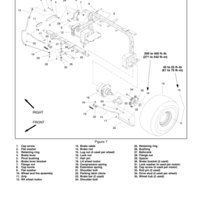
- Wheels
- Steering Column
- Brake Service
- Rear Wheel Bearings (2 Wheel Drive)
- Rear Axle
- Rear Axle Service
- Operator Seat
- Mechanical Seat Suspension
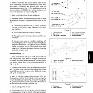
- Front Lift Arms
- Rear Lift Arms
- 7 – DPA Cutting Units
- Table of Contents
- Specifications
- General Information
- Cutting Unit Operator's Manual
- Special Tools
- Gauge Bar Assembly
- Bedknife Screw Tool
- Handle Assembly
- Plastic Plug
- Cutting Unit Kickstand
- Spline Insert Tool
- Rear Roller Bearing and Seal Installation Tools
- Turf Evaluator Tool
- Diameter, Circumference Measuring Tape
- Reel Bearing Installation Tool (cutting units with painted side plates)
- Cutting Reel Shim
- Cutting Performance Paper
- Pulley Alignment Tool
- Bedknife Top Angle Indicator and Mount
- Factors That Can Affect Cutting Performance
- Set Up and Adjustments
- Characteristics
- Reel Bearing Adjustment (cutting units with painted side plates)
- Leveling Rear Roller
- Service and Repairs
- Hydraulic Reel Motor
- Backlapping
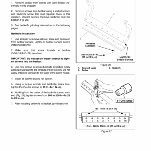
- Bedbar Assembly
- Bedknife Replacement and Grinding
- Bedbar Adjuster Service
- Reel Assembly (cutting units with painted side plates)
- Reel Assembly Service (cutting units with painted side plates)
- Reel Assembly (cutting units with aluminum side plates)
- Reel Assembly Service (cutting units with aluminum side plates)
- Preparing Reel for Grinding
- Front Roller
- Rear Roller
- Roller Service (greasable bearings with retaining ring)
- Roller Service (greasable bearings with bearing nut)
- Rear Roller Brush – Optional (cutting units with painted side plates)
- Rear Roller Brush – Optional (cutting units with aluminum side plates)
- 8 – Belt Driven Groomer (Optional)
- Grooming Performance
- Troubleshooting
- Adjustments
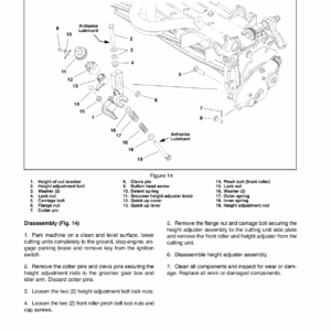
- Groomer Height, Depth Adjustment
- Service and Repairs
- Groomer Drive Belt Replacement
- Groomer Plate Assembly
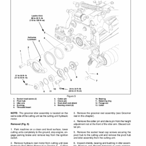
- Groomer Reel
- Groomer Reel Service
- Groomer Pivot Hub
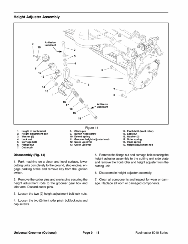
- Height Adjuster Assembly
- 9 – Universal Groomer (Optional)
- Table of Contents
- Grooming Performance
- Troubleshooting
- Groomer Reel Mechanical Problems
- Service and Repairs
- Gear Box Assembly
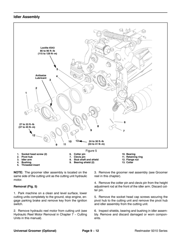
- Idler Assembly
- Groomer Reel
- Groomer Reel Service
- Grooming Brush (Optional) Service
- Height Adjuster Assembly
- 10 – Foldout Drawings
- Electrical Drawing Designations
- Hydraulic Schematic – 5210, 5410
- Hydraulic Schematic – 5510, 5610
- Electrical Schematic (Serial Number Below 310000000)
- Electrical Schematic (Serial Number Above 310000000)
- Glow Plug Circuits
- Crank Circuits
- Run (Transport) Circuits
- Run (Mow) Circuits
- Main Wire Harness Drawing (SN Below 310000000)
- Main Wire Harness Diagram (SN Below 310000000)
- Main Wire Harness Drawing (SN Above 310000000)
- Main Wire Harness Diagram (SN Above 310000000)
- Seat Wire Harness Drawing (SN Below 310000000)
- Seat Wire Harness Diagram (SN Below 310000000)
- Seat Wire Harness Drawing (SN Above 310000000)
- Seat Wire Harness Diagram (SN Above 310000000)
- Engine Wire Harness Drawing
- Engine Wire Harness Diagram
- Turf Defender Schematic
Be the first to review “Toro Reelmaster 5210, 5410, 5510, 5610 Series Service Repair Manual”
You must be logged in to post a review.

Reviews
There are no reviews yet.