
Toro Reelmaster 5010-H Service Repair Manual
$34.00
Manual Included:
- Service Repair Manual: 364 Pages
Specifications:
- Brand: Toro
- Model: Reelmaster 5010-H
- Type: Large Reel Mowers
- Manuals: Service Repair Manual
- Publication Numbers: 15212SL
- Language: English
- Format: PDF
- Description
- Reviews (0)
Description
Table of Content – Reelmaster 5010-H
- Title Page
- Revision History
- Reader Comments
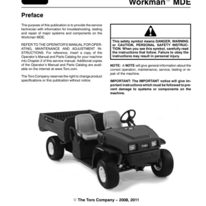
- Preface
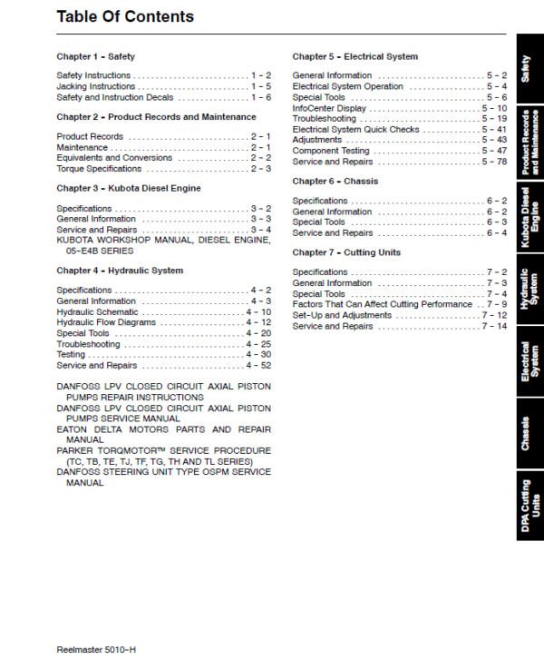
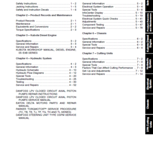
- Table Of Contents
- Table Of Contents (Continued)
- 1 – Safety
- Table of Contents
- Safety Instructions
- Before Operating
- While Operating
- Maintenance and Service
- Jacking Instructions
- Safety and Instruction Decals
- 2 – Product Records and Maintenance
- Table of Contents
- Product Records
- Maintenance
- Equivalents and Conversions
- Torque Specifications
- Fastener Identification
- Using a Torque Wrench with an Offset Wrench
- Standard Torque for Dry, Zinc Plated and Steel Fasteners (Inch Series)
- Standard Torque for Dry, Zinc Plated and Steel Fasteners (Metric Series)
- Other Torque Specifications
- Conversion Factors
- 3 – Kubota Diesel Engine
- Table of Contents
- Specifications
- General Information
- Traction Unit Operator’s Manual
- Kubota Workshop Manual
- 48 VDC Battery Disconnect
- Service and Repairs
- Air Cleaner Assembly
- Exhaust System
- Fuel System
- Radiator Assembly
- Engine
- Engine Removal
- Engine Installation
- Engine Bellhousing Assembly
- Kubota Workshop Manual, 05-E4B Series
- 4 – Hydraulic System
- Table of Contents
- Specifications
- General Information
- Traction Unit Operator’s Manual
- 48 VDC Battery Disconnect
- Check Hydraulic Fluid
- Towing Traction Unit
- Hydraulic Hoses
- Hydraulic Hose and Tube Installation
- Hydraulic Fitting Installation
- Relieving Hydraulic System Pressure
- Traction Circuit Component Failure
- Hydraulic Schematic
- Hydraulic Flow Diagrams
- Traction Circuit
- Lift Circuit: Raise Cutting Units
- Lift Circuit: Lower Cutting Units
- Steering Circuit
- Special Tools
- Troubleshooting
- General Hydraulic System Problems
- Traction Circuit Problems
- Lift Circuit Problems
- Steering Circuit Problems
- Testing
- Traction Circuit Relief Valve (R3) and (R4) Pressure Test
- Traction Circuit Charge Pressure Test
- Gear Pump (P2) Flow Test
- Front Wheel Motor Efficiency Test
- Piston (Traction) Pump Flow Test
- Lift Relief Valve (SVRV) Pressure Test
- Gear Pump (P1) Flow Test
- Lift Cylinder Internal Leakage Test
- Steering Relief Valve (R10) Pressure Test
- Steering Cylinder Internal Leakage Test
- Service and Repairs
- General Precautions for Removing and Installing Hydraulic System Components
- Check Hydraulic Lines and Hoses
- Flush Hydraulic System
- Filtering Closed- Loop Traction Circuit
- Hydraulic System Start- up
- Hydraulic Reservoir
- Piston (Traction) Pump Control Assembly
- Hydraulic Pump Assembly
- Piston (Traction) Pump Service
- Gear Pump Service
- Hydraulic Pump Drive Shaft
- Hydraulic Pump Drive Shaft Cross and Bearing Service
- Front Wheel Motors
- Front Wheel Motor Service
- Rear Wheel Motors (Machines with Optional CrossTrax Kit)
- Rear Wheel Motor Service (Machines with Optional CrossTrax Kit)
- Control Manifold Cartridge Valve Service
- Lift Control Manifold
- Lift Control Manifold Service
- CrossTrax AWD Manifold
- CrossTrax AWD Manifold Service
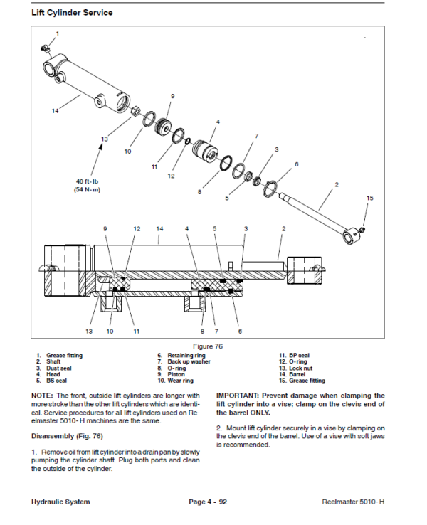
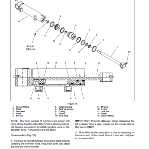
- Lift Cylinders
- Lift Cylinder Service
- Steering Control Valve
- Steering Control Valve Service
- Steering Cylinder
- Steering Cylinder Service
- Hydraulic Oil Cooler
- Danfoss LPV Closed Circuit Axial Piston Pumps Repair Manual
- Danfoss LPV Closed Circuit Axial Piston Pumps Service Instructions
- Eaton Delta Motors Parts and Repair Manual
- Parker Torqmotor Service Procedure (TC, TB, TE, TJ, TF, TG, TH, and TL Series)
- Danfoss Steering Unit Type OSPM Service Repair Manual
- 5 – Electrical System
- Table of Contents
- General Information
- Operator’s Manual
- Electrical Drawings
- 48 VDC Battery Disconnect
- Toro Electronic Controller
- CAN-bus Communications
- Electrical System Operation
- 12 VDC System Operation
- 48 VDC System Operation
- Special Tools
- InfoCenter Display
- Splash Screen
- Main Information Screens
- Access Protected Display Screens
- Main Menu Screen
- Faults Screen
- Service Screen
- Diagnostics Screen
- Settings Screen
- About Screen
- Troubleshooting
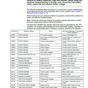
- Operator Advisories
- Fault Codes
- Starting Problems
- General Run and Transport Problems
- Cutting Unit Operating Problems
- Electrical System Quick Checks
- 12 VDC Battery Test (Open Circuit Test)
- Engine Charging System Test
- Glow Plug System Test
- Check Operation of Interlock Switches
- Adjustments
- Traction Neutral Switch
- Parking Brake Switch
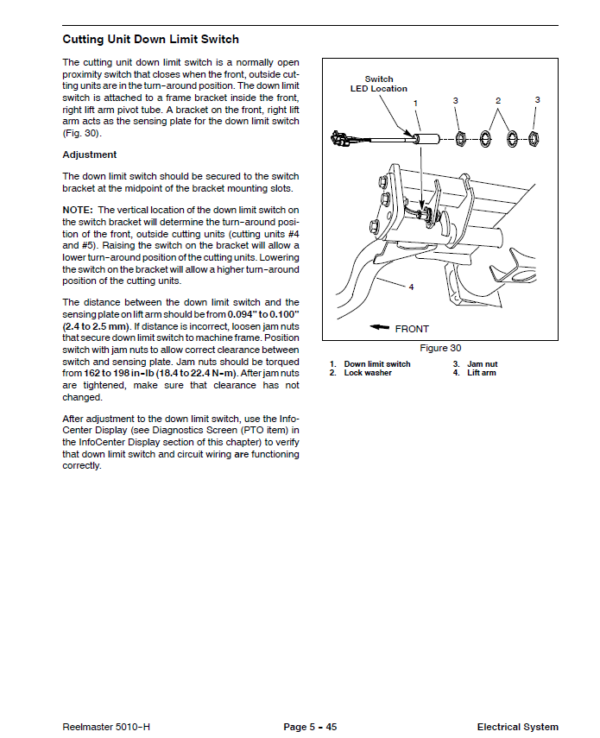
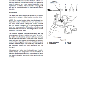
- Cutting Unit Down Limit Switch
- Mowith Transport Switch
- Component Testing
- Ignition Switch
- 12 VDC System Fuses
- 48 VDC System Fuses
- Engine Speed Switch
- Reel Engage, Disengage Switch
- Headlight Switch
- Seat Switch
- Parking Brake Switch
- Traction Neutral Switch
- Cutting Unit Down Limit Switch
- Joystick Raise and Lower Switches
- Mowith Transport Switch
- Main Power, Glow and 48 VDC Logic Relays
- Start Relay
- Main Contactor
- Toro Electronic Controller (TEC)
- Isolation Module
- Fusible Link Harness
- Diode Assembly
- 48 VDC System Protection Diode
- Location ID Module
- Cutting Reel Motor
- CAN-bus Termination Resistors
- Hydraulic Solenoid Valve Coil
- Temperature Sender
- Oil Pressure Switch
- Fuel Actuator
- Fuel Sender
- Fuel Pump
- Service and Repairs
- Hydraulic Solenoid Valve Coils
- 12 VDC Battery Service
- 48 VDC Battery Pack Service
- 48 VDC Electrical Power Connections
- Cutting Reel Motor
- Cutting Reel Motor Service
- Motor, Generator Assembly
- Motor, Generator Assembly Service
- 6 – Chassis
- Table of Contents
- Specifications
- General Information
- Traction Unit Operator’s Manual
- 48 VDC Battery Disconnect
- Special Tools
- Service and Repairs
- Wheels
- Steering Column
- Brake Service
- Rear Wheel Bearings (2 Wheel Drive)
- Rear Axle
- Rear Axle Service
- Control Arm
- Operator Seat
- Mechanical Seat Suspension
- Front Lift Arms
- Rear Lift Arms
- Hood
- 7 – Cutting Units
- Table of Contents
- Specifications
- General Information
- Cutting Unit Operator’s Manual
- 48 VDC Battery Disconnect
- Special Tools
- Factors That Can Affect Cutting Performance
- Set Up and Adjustments
- Characteristics
- Leveling Rear Roller
- Service and Repairs
- Cutting Reel Motor
- Backlapping
- Bedbar Assembly
- Bedknife Replacement and Grinding
- Bedbar Adjuster Service
- Cutting Reel Assembly Removal and Installation
- Cutting Reel Assembly Service
- Preparing Reel for Grinding
- Front Roller
- Rear Roller
- Roller Service
- Rear Roller Brush (Optional)
- Rear Roller Brush Drive System (Optional)
- 8 – Belt Driven Groomer (Optional)
- Table of Contents
- General Information
- Groomer Kit Installation Instructions
- 48 VDC Battery Disconnect
- Special Tools
- Grooming Performance
- Troubleshooting
- Groomer Reel Mechanical Problems
- Adjustments
- Groomer Height, Depth Adjustment
- Service and Repairs
- Groomer Drive Belt Replacement
- Groomer Drive Assembly
- Groomer Reel and Groomer Plate Assembly
- Groomer Reel Service
- Height Adjuster Assembly
- 9 – Universal Groomer (Optional)
- Table of Contents
- Grooming Performance
- Troubleshooting
- Groomer Reel Mechanical Problems
- Service and Repairs
- Gear Box Assembly
- Idler Assembly
- Groomer Reel
- Groomer Reel Service
- Grooming Brush (Optional) Service
- Height Adjuster Assembly
- 10 – Foldout Drawings
- Table of Contents
- Electrical Drawing Designations
- Hydraulic Schematic
- Electrical Schematic (Serial number below 403430000)
- Electrical Schematic(Serial numbers above 403430001)
- Main Wire Harness Drawing (Serial number below 403430000)
- Main Wire Harness Diagram (Serial number below 403430000)
- Main Wire Harness Drawing(Serial numbers 403430001 to 406599999)
- Main Wire Harness Drawing(Serial numbers 403430001 to 406599999)
- Main Wire Harness Drawing(Serial numbers above 406600000)
- Main Wire Harness Drawing(Serial numbers above 406600000)
- Seat Wire Harness Drawing
- Seat Wire Harness Diagram
Be the first to review “Toro Reelmaster 5010-H Service Repair Manual”
You must be logged in to post a review.
Reviews
There are no reviews yet.