 Service Repair Manual")
Toro Groundsmaster 5900, 5910 (Model 31698, 31600 – Tier 4) Service Repair Manual
$34.00
Manual Included:
- Service Repair Manual: 577 Pages
Specifications:
- Brand: Toro
- Model: Groundsmaster 5900, 5910 (Model 31698, 31600 – Tier 4)
- Type: Rotary Mowers
- Manuals: Service Repair Manual
- Publication Numbers: 16227SL
- Language: English
- Format: PDF
- Description
- Reviews (0)
Description
Table of Content – Groundsmaster 5900, 5910 (Model 31698, 31600 – Tier 4)
- Title Page
- Revision History
- Reader Comments
- NOTES
- Preface
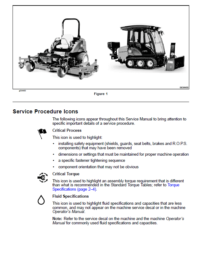
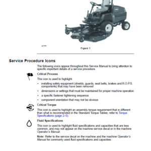
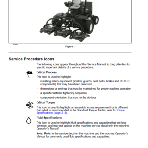
- Service Procedure Icons
- Table of Contents
- Chapter 1 : Safety
- Safety Instructions
- Before Operating the Machine
- While Operating the Machine
- Maintenance and Service
- Battery-Disconnect Switch
- Jacking Instructions
- Safety and Instructional Decals
- Chapter 2 : Specifications and Maintenance
- Specifications
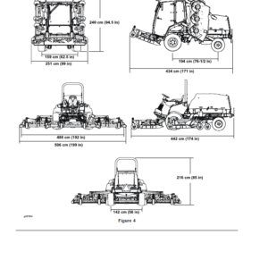
- Overall Dimensions
- Engine
- Hydraulic System
- Chassis
- Cutting Decks
- Torque Specifications
- Calculating the Torque Values When Using a Drive-Adapter Wrench
- Identifying the Fastener
- Standard Torque for Dry, Zinc Plated, and Steel Fasteners (Inch Series)
- Standard Torque for Dry, Zinc Plated, and Steel Fasteners (Metric Fasteners)
- Other Torque Specifications
- Conversion Factors
- Shop Supplies
- Special Tools
- Chapter 3 : Troubleshooting
- GEARS – The Systematic Approach to Defining, Diagnosing and Solving Problems
- Gather Information
- Evaluate Potential Causes
- Assess Performance
- Repair
- Solution Confirmation
- General Hydraulic System Problems
- Traction Circuit Problems
- PTO Problems
- Lift, Lower Circuit Problems
- Steering Circuit Problems
- Starting Problems
- General Run and Transport Problems
- Cutting Deck (PTO) Operating Problems
- Cutting Deck Lift, Lower Problems
- Operator Advisories
- TO START
- TO ENGAGE PTO
- TO SET CRUISE CONTROL
- TO LOWER DECK
- TO FLOAT DECK
- TO SET HIGH RANGE
- TO SET LOW RANGE
- FOR TRACTION
- ENGINE
- FUEL LEVEL
- TRACTION PEDAL
- TO RAISE DECK
- Using the InfoCenter Display for Troubleshooting
- Machine Faults
- Engine Faults
- Factors That Can Affect Quality of Cut and Clipping Dispersion
- Chapter 4 : Yanmar Diesel Engine
- General Information
- Operator’s Manuals
- Yanmar Service and Troubleshooting Manuals
- Stopping the Engine
- Engine Electronic Control Unit (ECU)
- Yanmar Engine
- Diesel Particulate Filter
- Service and Repairs
- Air Filter
- Exhaust System
- Fuel System
- Radiator
- Engine
- Pump Adapter Plate (Coupler)
- Yanmar TNV (Tier 4) Series Service Repair Manual
- Yanmar TNV (Tier 4) Series Troubleshooting Manual
- Chapter 5 : Hydraulic System
- General Information
- Operator’s Manual
- Relieving Hydraulic System Pressure
- Towing Traction Unit
- Traction Circuit Component Failure
- Hydraulic Hoses
- Installing Hydraulic Hoses and Tubes (O-Ring Face Seal)
- Installing the Hydraulic Fittings (SAE Straight Thread O-Ring Fittings)
- Hydraulic Schematic
- Hydraulic Flow Diagrams
- Traction Circuit Operation
- Traction Circuit: Low Range Traction Speed (Mow)
- Traction Circuit: High Range Traction Speed (Transport)
- Raise Cutting Deck
- Lower Cutting Deck
- PTO Mow Circuit
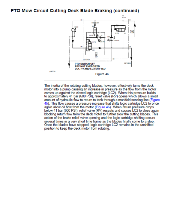
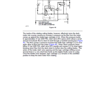
- PTO Mow Circuit Cutting Deck Blade Braking
- Steering Circuit
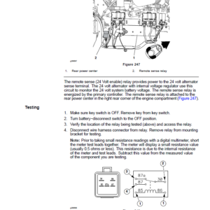
- Testing
- Before Performing Hydraulic Tests
- Precautions for Hydraulic Testing
- Which Hydraulic Tests Are Necessary?
- Traction Circuit Charge Pressure Test (Using Pressure Gauge)
- Traction Circuit Relief Pressure Test (Using Pressure Gauge)
- Counterbalance Pressure Test (Using Pressure Gauge)
- Piston (Traction) Pump Flow Test (Using Tester with Pressure Gauge & 40 GPM Flow Meter)
- Cutting Deck Circuit Pressure Test (Using Pressure Gauge)
- Cutting Deck Circuit Relief Pressure Test (Using Tester with Pressure Gauge and 40 GPM Flow Meter)
- Cutting Deck Motor Case Drain Leakage Test (Using Tester with Pressure Gauge & 40 GPM Flow Meter)
- Lift, Lower Circuit Relief Pressure Test (Using Pressure Gauge)
- Steering Circuit Relief Pressure Test (Using Pressure Gauge)
- Steering Cylinder Internal Leakage Test
- Gear Pump (PTO, Steering, Deck Lift, Lower and Traction Charge Circuits) Flow Test (Using Tester with Pressure Gauges and Flow Meter)
- Adjustments
- Adjust Manifold Relief Valves
- Service and Repairs
- General Precautions for Removing and Installing Hydraulic System Components
- Check Hydraulic Lines and Hoses
- Priming Hydraulic Pumps
- Flush Hydraulic System
- Charge Hydraulic System
- Filtering Closed−Loop Traction Circuit
- Hydraulic Reservoir
- Gear Pump
- Gear Pump Service
- Traction Circuit
- Piston (Traction) Pump
- Piston (Traction) Pump Service
- Front Wheel Motors
- Rear Wheel Motors
- Wheel Motor Service
- Traction Control Manifold
- Traction Control Manifold Service
- Brake Release Manifold
- Brake Release Manifold Service
- Cutting Deck Circuit
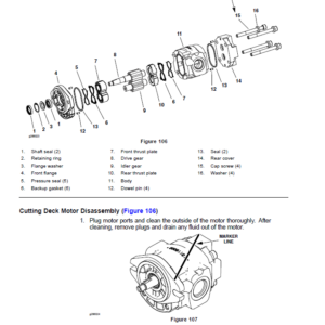
- Cutting Deck Motor
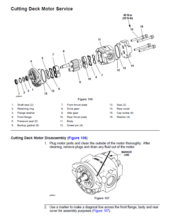
- Cutting Deck Motor Service
- Cutting Deck Control Manifolds
- Cutting Deck Control Manifold Service
- Steering and Cutting Deck Lift Circuits
- Steering Control Valve (For machines serial number below 403450000)
- Steering Control Valve (For machines serial number above 403450001)
- Steering Control Valve Service (For machines serial number below 40345000)
- Steering Control Valve Service (For machines serial number above 403450001)
- Steering Cylinders
- Steering Cylinder Service
- Front Cutting Deck Lift Cylinders
- Front Cutting Deck Lift Cylinder Service
- Wing Cutting Deck Lift Cylinders
- Wing Cutting Deck Lift Cylinder Service
- Steering, Deck Lift Control Manifold
- Steering, Deck Lift Control Manifold Service
- Cartridge Valve Service
- Hydraulic Oil Cooler
- Danfoss H1 Closed Circuit Axial Piston Pumps Service Repair Manual
- Danfoss H1 Closed Circuit Axial Piston pumps Repair Instructions
- Danfoss Steering Unit Type OSPM Service Repair Manual
- Eaton Parts And Repair Information: 5 Series Steering Control Units
- Chapter 6 : Electrical System
- General Information
- Operator’s Manual
- Operator Cab Components
- Toro Electronic Controllers (TEC)
- Engine Electronic Control Unit (ECU)
- Yanmar Engine Electrical Components
- Battery−Disconnect Switch
- Electrical System Operation
- 12 Volt System
- 24 Volt System
- CAN−bus Communications
- Electrical Drawings
- InfoCenter Display
- Operator Information Screen
- MAIN MENU
- SERVICE
- HOURS
- TRACTION PEDAL
- FAN OVERRIDE
- FAN DEMO
- REGENERATION
- DIAGNOSTICS SCREENS
- Electrical System Quick Checks
- Adjustments
- Cutting Deck Position Switch Adjustment
- Component Testing
- Fusible Link Harness
- Mega Fuses
- Fuses
- Battery−Disconnect Switch
- Toro Electronic Controllers (TECs)
- Key Switch
- PTO Switch
- Cutting Deck Raise, Lower Switches
- Throttle Switch
- High, Low Range Traction Speed Switch
- Cruise Control Switch
- Headlight Switch
- Turn Signal Switch
- Hazard Switch
- Parking Brake Switch
- Horn Button
- Contactors
- Seat Switch
- Windshield Wiper, Washer Switch (Groundsmaster 5910)
- Air Conditioning Switch (Groundsmaster 5910)
- Fan Speed Switch (Groundsmaster 5910)
- Work Light and Beacon Switches (Groundsmaster 5910 − Optional)
- Relays with Four (4) Terminals
- Relays with Five (5) Terminals
- Hydraulic Solenoid Valves
- Air Filter Service Indicator
- Fuel Sender
- Fuel Pump
- Hydraulic Oil Temperature Sender
- CAN−bus Terminator Resistor
- Resistor Assemblies
- Diode Assemblies
- Audible Alarm
- Traction Pedal Position Sensor
- Piston (Traction) Pump Control Solenoid Coils
- Cutting Deck Position Switches
- 24 Volt Cooling Fans
- 24 Volt Alternator
- 24 Volt Voltage Divider
- Fan Speed Switch (Machines with Two−Post ROPS Extension Operator Fan Kit)
- Resistor Module (Machines with Two−Post ROPS Extension Operator Fan Kit)
- Service and Repairs
- Batteries
- Hydraulic Solenoid Valve Coils
- 24 Volt Alternator, Air Conditioning Compressor Drive Belt
- 24 Volt Alternator
- Chapter 7 : Chassis
- General Information
- Operator’s Manual
- Service and Repairs
- Wheels
- Steering Column (For machines serial number below 403450000)
- Steering Column (For machines serial number above 403450001)
- Rear Axle
- Rear Axle Service
- Front Deck Lift Arms
- Wing Deck Lift Arms
- Wing Deck Lift Arm Joint Yoke
- Wing Deck Impact Arm Assembly
- Console Arm
- Traction Pedal
- Operator Seat
- Operator Seat Service
- Operator Seat Suspension
- Hood and Lower Shrouds
- Chapter 8 : Cutting Decks
- General Information
- Operator’s Manual
- Blade Stopping Time
- Service and Repairs
- Front Cutting Deck
- Front Cutting Deck Winglets
- Wing Cutting Decks
- Drive Belt Idler Assemblies
- Blade Spindles
- Blade Spindle Service
- Castor Forks and Wheels
- Deck Skids and Front Deck Roller ( and )
- Chapter 9 : Operator Cab
- General Information
- Operator’s Manual
- Electrical Components, Schematics and Wire Harness Drawings
- Air Conditioning System
- Cab Heater System
- Air Conditioning System Performance
- Service and Repairs
- General Precautions for Removing and Installing Air Conditioning System Components
- Air Conditioning Compressor
- Roof Assembly
- Heating and Air Conditioning Components
- A, C Condenser Fan Assembly
- A, C Condenser Assembly
- Mixing Box Assembly
- Heater and A, C Evaporator Cores
- Blower Fan
- Windshield Wiper Assembly
- Sanden SD Compressor Service Guide
- Appendix A: Foldout Drawings
- Electrical Drawing Designations
- Hydraulic Schematic
- Electrical Schematic (machine serial numbers below 316000200)
- Electrical Schematic (machine serial numbers below 316000200)
- Electrical Schematic (machine serial numbers 316000201 to 399999999)
- Electrical Schematic (machine serial numbers 316000201 to 399999999)
- Electrical Schematic (machine serial numbers 400000000 to 403450000)
- Electrical Schematic (machine serial numbers 400000000 to 403450000)
- Electrical Schematic (machine serial numbers 403450001 to 405600000)
- Electrical Schematic (machine serial numbers 403450001 to 405600000)
- Electrical Schematic (machine serial numbers 405600001 to 408000000)
- Electrical Schematic (machine serial numbers 405600001 to 408000000)
- Electrical Schematic (machine serial numbers above 408000000)
- Electrical Schematic (machine serial numbers above 408000000)
- Operator Platform Wire Harness Drawing (machine serial numbers below 316000200)
- Operator Platform Wire Harness Diagram (machine serial numbers below 316000200)
- Operator Platform Wire Harness Diagram (machine serial numbers below 316000200)
- Operator Platform Wire Harness Drawing (machine serial numbers 316000201 to 316999999)
- Operator Platform Wire Harness Diagram (machine serial numbers 316000201 to 316999999)
- Operator Platform Wire Harness Diagram (machine serial numbers 316000201 to 316999999)
- Operator Platform Wire Harness Diagram (machine serial numbers 400000000 to 403450000)
- Operator Platform Wire Harness Diagram (machine serial numbers 400000000 to 403450000)
- Operator Platform Wire Harness Diagram (machine serial numbers 400000000 to 403450000)
- Operator Platform Wire Harness Diagram (machine serial numbers 403450001 to 405600000)
- Operator Platform Wire Harness Diagram (machine serial numbers 403450001 to 405600000)
- Operator Platform Wire Harness Diagram (machine serial numbers 403450001 to 405600000)
- Operator Platform Wire Harness Drawing (machine serial numbers 405600001 to 408000000)
- Operator Platform Wire Harness Diagram (machine serial numbers 405600001 to 408000000)
- Operator Platform Wire Harness Drawing (machine serial numbers above 408000000)
- Operator Platform Wire Harness Diagram (machine serial numbers above 408000000)
- Rear Wire Harness Drawing (machine serial numbers below 316000200)
- Rear Wire Harness Diagram (machine serial numbers below 316000200)
- Rear Wire Harness Drawing (machine serial numbers 316000201 to 403450000)
- Rear Wire Harness Drawing (machine serial numbers 316000201 to 403450000)
- Rear Wire Harness Drawing (machine serial numbers 403450001 to 405600000)
- Rear Wire Harness Drawing (machine serial numbers 403450001 to 405600000)
- Rear Wire Harness Drawing (machine serial numbers 405600001 to 408000000)
- Rear Wire Harness Diagram (machine serial numbers 405600001 to 408000000)
- Rear Wire Harness Drawing (machine serial numbers above 408000000)
- Rear Wire Harness Diagram (machine serial numbers above 408000000)
- Engine Wire Harness Drawing (machine serial numbers 316000001 to 316999999)
- Engine Wire Harness Drawing (machine serial numbers 316000001 to 316999999)
- Engine Wire Harness Drawing (machine serial numbers 400000000 to 403450000)
- Engine Wire Harness Drawing (machine serial numbers 400000000 to 403450000)
- Engine Wire Harness Drawing (machine serial numbers above 403450001)
- Engine Wire Harness Drawing (machine serial numbers above 403450001)
- Engine DPF Wire Harness Drawing (machine serial numbers above 408000000)
- NO TITLE
- Cab Power Supply Wire Harness (Machine serial numbers below 316000200)
- Cab Headliner Wire Harness Drawing (Machine serial numbers below 308000000)
- Cab Headliner Wire Harness Diagram (Machine serial numbers below 308000000)
- Cab Headliner Wire Harness Drawing (Machine serial numbers above 308000000)
- Cab Headliner Wire Harness Diagram (Machine serial numbers above 308000000)
- Wire Harness Diagram − Two−Post ROPS Extension
- Wire Harness Diagram − Two−Post ROPS Extension
Be the first to review “Toro Groundsmaster 5900, 5910 (Model 31698, 31600 – Tier 4) Service Repair Manual”
You must be logged in to post a review.
Reviews
There are no reviews yet.