 Service Repair Manual")
Toro Groundsmaster 4500-D, 4700-D (Models 30885, 30887, 30893, 30893TE, 30899, 30899TE) Service Repair Manual
$34.00
Manual Included:
- Service Repair Manual: 492 Pages
Specifications:
- Brand: Toro
- Model: Groundsmaster 4500-D, 4700-D (Models 30885, 30887, 30893, 30893TE, 30899, 30899TE)
- Type: Rotary Mowers
- Manuals: Service Repair Manual
- Publication Numbers: 19245SL
- Language: English
- Format: PDF
- Description
- Reviews (0)
Description
Table of Content – Groundsmaster 4500-D, 4700-D (Models 30885, 30887, 30893, 30893TE, 30899, 30899TE)
- Title Page
- Revision History
- Reader Comments
- NOTES
- Preface
- Service Procedure Icons
- Table of Contents
- Chapter 1 : Safety
- Safety Instructions
- Before Operating the Machine
- While Operating the Machine
- Maintenance and Service
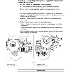
- Jacking Instructions
- Safety and Instructional Decals
- Chapter 2 : Specifications and Maintenance
- Specifications
- Overall Dimensions
- Engine (Models 30893, 30893TE, 30899 and 30899TE)
- Engine (Models 30885 and 30887)
- Hydraulic System
- Axles, Planetaries and Brakes
- Cutting Decks
- Torque Specifications
- Calculating the Torque Values When Using a Drive-Adapter Wrench
- Identifying the Fastener
- Standard Torque for Dry, Zinc Plated, and Steel Fasteners (Inch Series)
- Standard Torque for Dry, Zinc Plated, and Steel Fasteners (Metric Fasteners)
- Other Torque Specifications
- Conversion Factors
- Shop Supplies
- Special Tools
- Chapter 3 : Troubleshooting
- GEARS – The Systematic Approach to Defining, Diagnosing and Solving Problems
- Gather Information
- Evaluate Potential Causes
- Assess Performance
- Repair
- Solution Confirmation
- General Hydraulic System Problems
- Traction Problems
- Mow Problems
- Steering Problems
- Lift Problems
- Engine Cooling Fan Problems
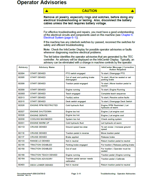
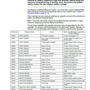
- Operator Advisories
- Machine Fault Codes
- Starting Problems
- General Run and Transport Problems
- Cutting Deck Operating Problems
- Cutting Deck Lift, Lower Problems
- Aftercut Appearance
- Chapter 4 : Yanmar Diesel Engine
- General Information
- Operator’s Manual
- Yanmar Service and Troubleshooting Manuals
- Stopping the Engine
- Engine Electronic Control Unit (ECU)
- Yanmar Engine: Models 30893, 30893TE, 30899 and 30899TE
- Yanmar Engine: Models 30885 and 30887
- Diesel Particulate Filter
- Service and Repairs
- Air Cleaner System
- Fuel System
- Radiator and Oil Cooler Assembly
- Engine
- Pump Adaptor Plate
- Exhaust System (Models 30885 and 30887)
- Yanmar TNV (Tier 4i) Series Service Repair Manual
- Yanmar TNV (Tier 4i) Series Troubleshooting Manual
- Yanmar TNV (Tier 4) Series Service Repair Manual
- Yanmar TNV (Tier 4) Series Troubleshooting Manual
- Chapter 5 : Hydraulic System
- General Information
- Operator’s Manual
- Check Hydraulic Fluid
- Towing Traction Unit
- Relieving Hydraulic System Pressure
- Traction Circuit Component Failure
- Hydraulic Hoses
- Installing Hydraulic Hoses and Tubes (O-Ring Face Seal)
- Installing the Hydraulic Fittings (SAE Straight Thread O-Ring Fittings)
- Hydraulic Schematic
- Hydraulic Flow Diagrams
- Traction Circuit: LOW Speed
- Traction Circuit: HIGH Speed
- Lower Cutting Decks: Groundsmaster 4500-D
- Lower Cutting Decks: Groundsmaster 4700-D
- Raise Cutting Decks: Groundsmaster 4500-D
- Raise Cutting Decks: Groundsmaster 4700-D
- Mow Circuit
- Cutting Deck Blade Braking
- Steering Circuit
- Engine Cooling Fan Circuit
- Testing
- Precautions for Hydraulic Testing
- Which Hydraulic Tests Are Necessary?
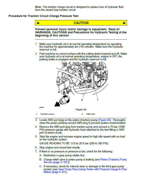
- Traction Circuit Charge Pressure (Using Pressure Gauge)
- Traction Circuit Relief Pressure (Using Pressure Gauge)
- Reverse Traction Circuit Reducing Valve (PR) Pressure (Using Pressure Gauge)
- Rear Traction Circuit Relief (RV) Pressure (Using Pressure Gauge)
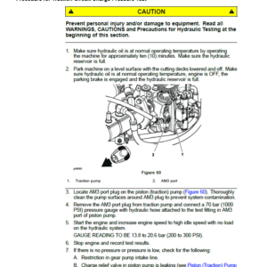
- Piston (Traction) Pump Flow (Using Tester with Pressure Gauge & Flow Meter)
- Cutting Deck Circuit Pressure (Using Pressure Gauge)
- Cutting Deck Circuit Relief Pressure (Using Tester with Pressure Gauge & Flow Meter)
- Deck Motor Case Drain Leakage (Using Tester with Pressure Gauge & Flow Meter)
- Steering Circuit Relief Pressure (Using Pressure Gauge)
- Steering Cylinder Internal Leakage
- Lift, Lower Circuit Relief Pressure (Using Pressure Gauge)
- Engine Cooling Fan Circuit (Using Pressure Gauge and Phototac)
- Gear Pump Flow (Using Tester with Pressure Gauge & Flow Meter)
- Procedure for Gear Pump Flow Test
- Adjustments
- Adjust Control Manifold Relief Valves
- Service and Repairs
- General Precautions for Removing and Installing Hydraulic System Components
- Check Hydraulic Lines and Hoses
- Priming Hydraulic Pumps
- Flush Hydraulic System
- Filtering Closed−Loop Traction Circuit
- Charge Hydraulic System
- Gear Pump
- Gear Pump Service
- Piston (Traction) Pump
- Piston (Traction) Pump Service
- Rear Traction Control Manifold
- Rear Traction Manifold Service
- Control Manifold Cartridge Valve Service
- Two Speed Shift Manifold
- Rear Axle Motor
- Front Wheel Motors
- Rear Axle and Front Wheel Motor Service
- Cutting Deck Motor
- Cutting Deck Motor Service
- Deck Control Manifold
- Deck Control Manifold Service (GM4500-D)
- Deck Control Manifold Service (GM4700-D)
- Steering Control Valve
- Steering Control Valve Service
- Steering Cylinder
- Steering Cylinder Service
- Engine Cooling Fan Motor
- Engine Cooling Fan Motor Service
- Fan Control Manifold
- Fan Control Manifold Service
- Lift Control Manifold
- Lift Control Manifold Service (GM4500-D)
- Lift Control Manifold Service (GM4700-D)
- Lift Circuit Junction Manifold
- Lift Cylinders: Decks #1, #4 and #5
- Lift Cylinders: Decks #2 and #3
- Lift Cylinders: Decks #6 and #7 (GM4700-D)
- Lift Cylinder Service
- Hydraulic Reservoir
- Radiator and Oil Cooler Assembly
- Danfoss K And L Frame Variable Motors Service Repair Manual
- Danfoss Steering Unit Type OSPM Service Repair Manual
- Danfoss MP1 Closed Circuit Axial Piston Pumps Service Repair Manual
- Chapter 6 : Electrical System
- General Information
- Operator's Manual
- Electrical Drawings
- Toro Electronic Controllers (TEC)
- Engine Electronic Control Unit (ECU)
- Yanmar Engine Electrical Components
- CAN−bus Communications
- Electrical Drawings
- InfoCenter Display
- Adjustments
- Traction Pedal Adjustment
- Traction Pedal Position Sensor Calibration
- Traction Pump Swashplate Angle Sensor Calibration
- Electrical System Quick Checks
- Battery Test (Open Circuit)
- Charging System Test
- Check Operation of Interlock Switches
- Component Testing
- Ignition Switch
- Fuses
- Fusible Link Harness
- PTO Switch
- High, Low Speed, Engine Speed Request and Cutting Deck Lift Switches
- Headlight Switch
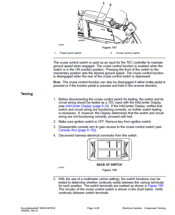
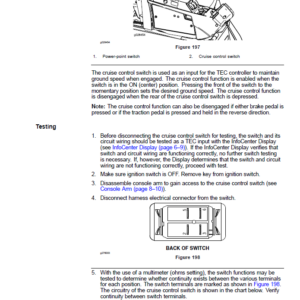
- Cruise Control Switch
- Seat Switch
- Parking Brake Switch
- Service Brake Switches
- Cutting Deck Position Switches
- Relays with Four (4) Terminals
- Relays with Five (5) Terminals
- Traction Pedal Position Sensor
- Swashplate Angle Sensor
- Toro Electronic Controllers (TEC)
- Hydraulic Solenoid Valve Coils
- Piston (Traction) Pump Control Solenoid Coils
- Hydraulic Oil Temperature Sender
- Traction Pressure Sensor
- Fuel Pump (Models 30893, 30893TE, 30899 and 30899TE)
- Fuel Pump (Models 30885 and 30887)
- CAN−bus Termination Resistor
- Diode Assemblies
- Resistor Assembly
- Capacitor Assembly
- Fan Speed Switch (Machines with Two−Post ROPS Extension Operator Fan Kit)
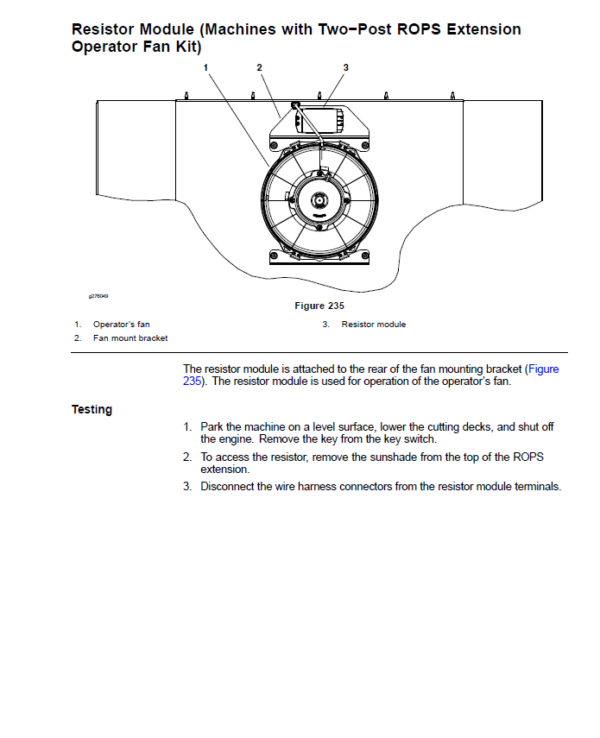
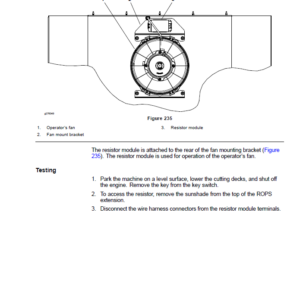
- Resistor Module (Machines with Two−Post ROPS Extension Operator Fan Kit)
- Service and Repairs
- Battery Care
- Battery Storage
- Battery Service
- Chapter 7 : Axles, Planetaries and Brakes
- General Information
- Operator’s Manual
- Adjustments
- Planetary Drive Assembly Endplay
- Service and Repairs
- Brake Assembly
- Brake Inspection and Repair
- Planetary Drive Assembly
- VA02 Series Planetary Drive Service
- Rear Axle Assembly
- Rear Axle Service
- Bevel Gear Case and Axle Case
- Differential Shafts
- Axle Shafts
- Input Shaft, Pinion Gear
- Differential Gear
- Pinion Gear to Ring Gear Engagement
- Gear Pattern Movement Summary
- Chapter 8 : Chassis
- General Information
- Operator’s Manual
- Cutting Deck Identification
- Service and Repairs
- Steering Column
- Traction Pedal
- Console Arm
- Lift Arms for Cutting Decks #1, #4 and #5
- Lift Arms for Cutting Decks #2 and #3
- Lift Arms for Cutting Decks #6 and #7 (Groundsmaster 4700-D)
- Operator Seat
- Operator Seat Service
- Operator Seat Suspension
- Hood
- Chapter 9 : Cutting Decks
- General Information
- Operator’s Manual
- Adjustments
- Blade Stopping Time
- Service and Repairs
- Blade Spindle Assembly
- Blade Spindle Service
- Rear Roller
- Rear Roller Service
- Front Roller Service
- Cutting Deck Carrier Frame
- Appendix A: Foldout Drawings
- Electrical Drawing Designations
- Hydraulic Schematic – Groundsmaster 4500-D
- Hydraulic Schematic – Groundsmaster 4700-D
- Electric Schematic – Groundsmaster 4500-D, 4700-D (Models 30885 and 30887)
- Electric Schematic – Groundsmaster 4500-D, 4700-D (Models 30893, 30893TE, 30899 and 30899TE)
- Optional Operator Cab Electrical Schematic – Groundsmaster 4500-D, 4700-D
- Main Wire Harness – Groundsmaster 4500-D, 4700-D
- Main Wire Harness – Groundsmaster 4500-D, 4700-D
- Seat and Console Wire Harness – Groundsmaster 4500-D, 4700-D
- Seat and Console Wire Harness – Groundsmaster 4500-D, 4700-D
- Power Center Wire Harness – Groundsmaster 4500-D, 4700-D
- Power Center Wire Harness – Groundsmaster 4500-D, 4700-D
- Deck 6 and 7 Wire Harness – Groundsmaster 4700-D
- Deck 6 and 7 Wire Harness – Groundsmaster 4700-D
- Engine Wire Harness Drawing – Groundsmaster 4500−D, 4700−D (Models 30885 and 30887) (Serial Numbers Below 408000000)
- Engine Wire Harness Drawing – Groundsmaster 4500−D, 4700−D (Models 30885 and 30887) (Serial Numbers Below 408000000)
- Engine Wire Harness Drawing – Groundsmaster 4500−D, 4700−D (Models 30885 and 30887) (Serial Numbers Above 408000000)
- Engine Wire Harness Drawing – Groundsmaster 4500−D, 4700−D (Models 30885 and 30887) (Serial Numbers Above 408000000)
- Engine DPF Wire Harness Drawing – Groundsmaster 4500−D, 4700−D (Models 30885 and 30887) (Serial Numbers Above 408000000)
- NO TITLE
- Engine Wire Harness Drawing – Groundsmaster 4500−D, 4700−D (Models 30893, 30893TE, 30899 and 30899TE)
- Engine Wire Harness Drawing – Groundsmaster 4500−D, 4700−D (Models 30893, 30893TE, 30899 and 30899TE)
- Wire Harness Diagram – Two−Post ROPS Extension
- Wire Harness Diagram – Two−Post ROPS Extension
Be the first to review “Toro Groundsmaster 4500-D, 4700-D (Models 30885, 30887, 30893, 30893TE, 30899, 30899TE) Service Repair Manual”
You must be logged in to post a review.
Reviews
There are no reviews yet.