 Service Repair Manual")
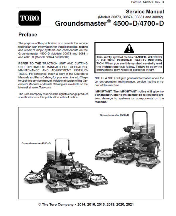
Toro Groundsmaster 4500-D, 4700-D (Models 30873, 30874, 30881, 30882) Service Repair Manual
$34.00
Manual Included:
- Service Repair Manual: 390 Pages
Specifications:
- Brand: Toro
- Model: Groundsmaster 4500-D, 4700-D (Models 30873, 30874, 30881, 30882) REVISED
- Type: Rotary Mowers
- Manuals: Service Repair Manual
- Publication Numbers: 14205SL
- Language: English
- Format: PDF
- Description
- Reviews (0)
Description
Table of Content – Groundsmaster 4500-D, 4700-D (Models 30873, 30874, 30881, 30882) REVISED
- Title Page
- Revision History
- Reader Comments
- Preface
- Table Of Contents
- 1 – Safety
- Table of Contents
- General Safety Instructions
- Before Operating
- While Operating
- Maintenance and Service
- Jacking Instructions
- Safety and Instruction Decals
- 2 – Product Records and Maintenance
- Table of Contents
- Product Records
- Maintenance
- Equivalents and Conversions
- Decimal and Millimeter Equivalents
- U.S. to Metric Conversions
- Torque Specifications
- Fastener Identification
- Using a Torque Wrench with an Offset Wrench
- Standard Torque for Dry, Zinc Plated and Steel Fasteners (Inch Series)
- Standard Torque for Dry, Zinc Plated and Steel Fasteners (Metric Series)
- Other Torque Specifications
- Conversion Factors
- 3 – Yanmar Diesel Engine
- Table of Contents
- Specifications (Models 30873 and 30874)
- Specifications (Models 30881 and 30882)
- General Information
- Operator’s Manuals
- Yanmar Service and Troubleshooting Manuals
- Stopping the Engine
- Engine Electronic Control Unit (ECU)
- Yanmar Engine: Models 30873 and 30874
- Yanmar Engine: Models 30881 and 30882
- Diesel Particulate Filter (DPF)
- Service and Repairs
- Air Cleaner System
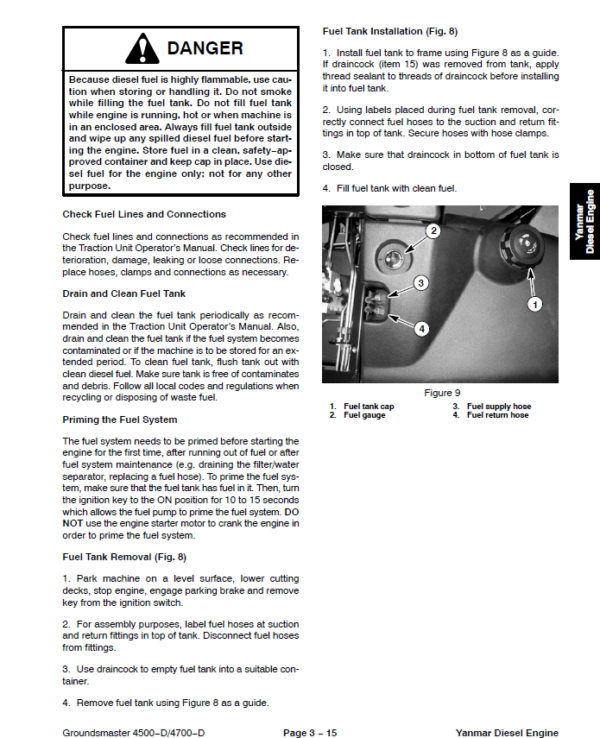
- Fuel System
- Radiator and Oil Cooler Assembly
- Engine
- Pump Adapter Plate
- Exhaust System (Models 30881 and 30882)
- YANMAR TNV (Tier 4i) SERIES Service Repair Manual
- YANMAR TNV (Tier 4i) SERIES TROUBLESHOOTING
MANUAL - YANMAR TNV (Tier 4) SERIES Service Repair Manual
- YANMAR TNV (Tier 4) SERIES TROUBLESHOOTING
MANUAL - 4 – Hydraulic System
- Table of Contents
- Specifications
- General Information
- Operator’s Manual
- Check Hydraulic Fluid
- Towing Traction Unit
- Relieving Hydraulic System Pressure
- Traction Circuit Component Failure
- Hydraulic Hoses
- Hydraulic Hose and Tube Installation (O-Ring Face Seal Fitting)
- Hydraulic Fitting Installation (SAE Straight Thread O-Ring Fitting into Component Port)
- Hydraulic Schematics
- Groundsmaster 4500-D
- Grondsmaster 4700-D
- Hydraulic Flow Diagrams
- Traction Circuit: LOW Speed
- Traction Circuit: HI Speed
- Lower Cutting Decks (GM4500-D)
- Lower Cutting Decks (GM4700-D)
- Raise Cutting Decks (GM4500-D)
- Raise Cutting Decks (GM4700-D)
- Mow Circuit
- Cutting Deck Blade Braking
- Steering Circuit
- Engine Cooling Fan Circuit
- Special Tools
- Troubleshooting
- General Hydraulic System Problems
- Traction Circuit Problems
- Mow Circuit Problems
- Steering Circuit Problems
- Lift, Lower Circuit Problems
- Engine Cooling Fan Circuit Problems
- Testing
- Traction Circuit Charge Pressure
- Traction Circuit Relief Pressure
- Reverse Traction Circuit Reducing Valve (PR) Pressure
- Rear Traction Circuit Relief (RV) Pressure
- Piston (Traction) Pump Flow
- Cutting Deck Circuit Pressure
- Cutting Deck Circuit Relief Pressure
- Deck Motor Case Drain Leakage
- Steering Circuit Relief Pressure
- Steering Cylinder Internal Leakage
- Lift, Lower Circuit Relief Pressure
- Engine Cooling Fan Circuit
- Gear Pump Flow
- Adjustments
- Adjust Control Manifold Relief Valves
- Service and Repairs
- General Precautions for Removing and Installing Hydraulic System Components
- Check Hydraulic Lines and Hoses
- Priming Hydraulic Pumps
- Flush Hydraulic System
- Filtering Closed-Loop Traction Circuit
- Charge Hydraulic System
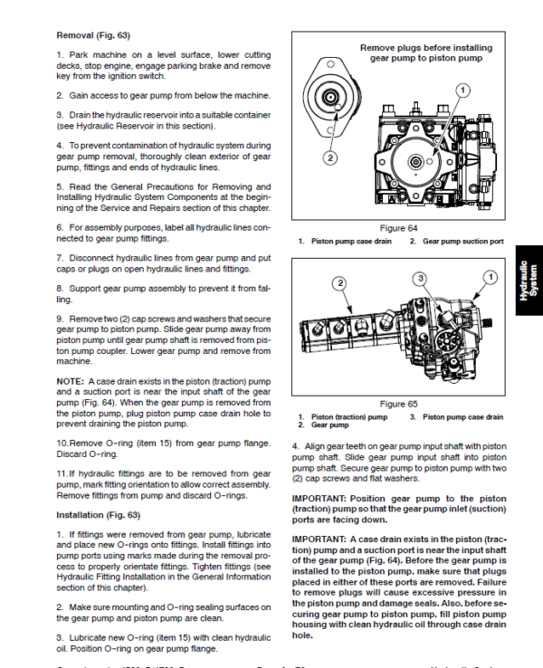
- Gear Pump
- Gear Pump Service
- Piston (Traction) Pump
- Piston (Traction) Pump Service
- Rear Traction Control Manifold
- Rear Traction Control Manifold Service
- Control Manifold Cartridge Valve Service
- HI, LOW Range Control Manifold
- Rear Axle Motor
- Front Wheel Motors
- Rear Axle and Front Wheel Motor Service
- Cutting Deck Motor
- Cutting Deck Motor Service
- Deck Control Manifold
- Deck Control Manifold Service (GM 4500-D)
- Deck Control Manifold Service (GM 4700-D)
- Steering Control Valve
- Steering Control Valve Service
- Steering Cylinder
- Steering Cylinder Service
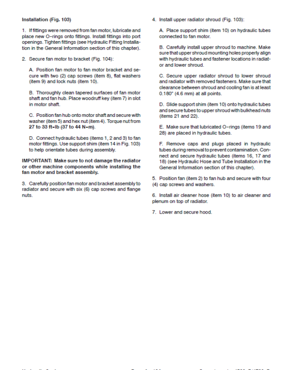
- Engine Cooling Fan Motor
- Engine Cooling Fan Motor Service
- Fan Control Manifold
- Fan Control Manifold Service
- Lift Control Manifold
- Lift Control Manifold Service (GM 4500-D)
- Lift Control Manifold Service (GM 4700-D)
- Lift Circuit Junction Manifold
- Lift Cylinders: Decks #1, #4 and #5
- Lift Cylinders: Decks #2 and #3
- Lift Cylinders: Decks #6 and #7 (GM 4700-D)
- Lift Cylinder Service
- Hydraulic Reservoir
- Radiator and Oil Cooler Assembly
- DANFOSS H1 AXIAL PISTON PUMPS Service Repair Manual
- DANFOSS H1 AXIAL PISTON PUMPS REPAIR INSTRUCTIONS
- DANFOSS MP1 CLOSED CIRCUIT AXIAL PISTON PUMPS Service Repair Manual
- DANFOSS K and L MOTORS Service Repair Manual
- DANFOSS STEERING UNIT OSPM Service Repair Manual
- 5 – Electrical System
- Table of Contents
- General Information
- Operator’s Manual
- Electrical Drawings
- Toro Electronic Controllers (TEC)
- Yanmar Engine Electronic Control Unit (ECU)
- Yanmar Engine Electrical Components
- CAN-bus Communications
- Special Tools
- InfoCenter Display
- Splash Screens
- Main Information Screens
- Main Menu Screen
- Faults Screen
- Service Screen
- Diagnostics Screen
- Settings Screen
- About Screen
- Troubleshooting
- Operator Advisories
- Fault Codes
- Starting Problems
- General Run and Transport Problems
- Cutting Deck Operating Problems
- Cutting Deck Lift, Lower Problems
- Electrical System Quick Checks
- Battery Test (Open Circuit Test)
- Charging System Test
- Check Operation of Interlock Switches
- Adjustments
- Traction Pedal Adjustment
- Traction Pedal Position Sensor Calibration
- Component Testing
- Ignition Switch
- Fuses
- Fusible Link Harness
- PTO Switch
- Hi, Low Speed, Engine Speed Request and Cutting Deck Lift Switches
- Headlight Switch
- Seat Switch
- Parking Brake Switch
- Cutting Deck Position Switches
- Relays with Four (4) Terminals
- Relays with Five (5) Terminals
- Traction Pedal Position Sensor
- Toro Electronic Controllers (TEC)
- Hydraulic Solenoid Valve Coils
- Piston (Traction) Pump Control Solenoid Coils
- Hydraulic Oil Temperature Sender
- Fuel Pump (Models 30873 and 30874)
- Fuel Pump (Models 30881 and 30882)
- CAN-bus Termination Resistor
- Diode Assemblies
- Resistor Assemblies
- Fan Speed Switch (Machines with Two−Post ROPS Extension Operator Fan Kit)
- Resistor Module (Machines with Two−Post ROPS Extension Operator Fan Kit)
- Service and Repairs
- Battery Care
- Battery Storage
- Battery Service
- Battery Removal and Installation
- Battery Inspection and Maintenance
- Battery Testing
- Battery Charging
- 6 – Axles, Planetaries and Brakes
- Table of Contents
- Specifications
- General Information
- Operator's Manual
- Adjustments
- Planetary Drive Endplay (OPH-2 series planetary drives)
- Service and Repairs
- Brake Assembly
- Brake Inspection and Repair
- Planetary Drive Assembly
- OPH-2 Series Planetary Drive Service
- VA02 Series Planetary Drive Service
- Rear Axle Assembly
- Rear Axle Service
- Bevel Gear Case and Axle Case
- Differential Shafts
- Axle Shafts
- Input Shaft, Pinion Gear
- Differential Gear
- Pinion Gear to Ring Gear Engagement
- 7 – Chassis
- Table of Contents
- General Information
- Operator’s Manual
- Cutting Deck Identification
- Service and Repairs
- Steering Column
- Traction Pedal
- Console Arm
- Lift Arms for Cutting Decks #1, #4 and #5
- Lift Arms for Cutting Decks #2 and #3
- Lift Arms for Cutting Decks #6 and #7 (GM 4700-D)
- Operator Seat
- Operator Seat Service
- Operator Seat Suspension
- Hood
- 8 – Cutting Decks
- Table of Contents
- Specifications
- General Information
- Operator’s Manual
- Troubleshooting
- Factors That Can Affect Quality of Cut
- Special Tools
- Adjustments
- Blade Stopping Time
- Service and Repairs
- Blade Spindle Assembly
- Blade Spindle Service
- Rear Roller
- Rear Roller Service
- Front Roller Service
- Cutting Deck Carrier Frame
- 9 – Foldout Drawings
- Electrical Drawing Designations
- Groundsmaster 4500–D Hydraulic Schematic
- Groundsmaster 4500–D With Optional Flow Divider Kit Hydraulic Schematic
- Groundsmaster 4700–D Hydraulic Schematic
- Groundsmaster 4700–D With Optional Flow Divider Kit Hydraulic Schematic
- Electrical Schematic
Groundsmaster 4500–D, 4700–D
Models 30881 and 30882
(Serial numbers below 315000300) - Electrical Schematic Groundsmaster 4500–D, 4700–DModels 30873 and 30874(Serial numbers below 315000300)
- Groundsmaster 4500–D, 4700–D
Electrical Schematic
Models 30881 and 30882
(Serial Numbers 315000301 to 399999999) - Groundsmaster 4500–D, 4700–D Electrical Schematic Models 30873 and 30874 (Serial Numbers 315000301 to 399999999)
- Groundsmaster 4500–D, 4700–D Electrical Schematic Models 30881 and 30882(Serial Numbers 400000000 to 403450000)
- Groundsmaster 4500–D, 4700–D Electrical Schematic Models 30873 and 30874(Serial Numbers 400000000 to 403450000)
- Groundsmaster 4500–D, 4700–D Electrical Schematic (Serial Numbers Serial Numbers 403450001 to 408000000)Models 30881 and 30882
- Groundsmaster 4500–D, 4700–DElectrical Schematic(Serial Numbers Above 408000000)
- Groundsmaster 4500–D, 4700–D Electrical Schematic (Serial Numbers Above 403450001) Models 30873 and 30874
- Electrical Schematic Groundsmaster 4500–D, 4700–D Optional Operator Cab (Serial number below 399999999)
- Groundsmaster 4500–D, 4700–D Electrical Schematic Optional Operator Cab (Serial Numbers Above 400000000)
- Groundsmaster 4500–D, 4700–D Main Wire Harness (Serial number below 315000300)
- Groundsmaster 4500–D, 4700–D Main Wire Harness (Serial Numbers 315000301 to 399999999)
- Groundsmaster 4500–D, 4700–D Main Wire Harness (Serial Numbers 400000000 to 403450000)
- Groundsmaster 4500–D, 4700–D Main Wire Harness (Serial Numbers Above 403450001)
- Groundsmaster 4500–D, 4700–D Seat and Console Wire Harness (Serial number below 399999999)
- Groundsmaster 4500–D, 4700–D Seat and Console Wire Harness (Serial Numbers 400000000 to 403450000)
- Groundsmaster 4500–D, 4700–D Seat and Console Wire Harness (Serial Numbers Above 403450001)
- Groundsmaster 4500–D, 4700–D Power Center Wire Harness(Serial number below 403450000)
- Groundsmaster 4500–D, 4700–D Power Center Wire Harness(Serial Numbers Above 403450001)
- Deck 6 and 7 Wire Harness Groundsmaster 4700–D
- (Models 30881 and 30882) Engine Wire Harness Drawing Groundsmaster 4500–D, 4700–D (Serial number below 315000000)
- Groundsmaster 4500–D, 4700–D (Models 30881 and 30882) Engine Wire Harness Drawing(Serial Numbers 315000001 to 408000000)
- Groundsmaster 4500–D, 4700–D(Models 30881 and 30882)Engine Wire Harness Drawing(Serial Numbers Above 408000000)
- Groundsmaster 4500–D, 4700–D(Models 30881 and 30882)Engine DPF Sub–Wire Harness Drawing(Serial Numbers Above 408000000)
- (Models 30873 and 30874) Engine Wire Harness Drawing Groundsmaster 4500–D, 4700–D
- Groundsmaster 4500–D, 4700–D Wire Harness Diagram — Two–Post ROPS Extension
- Groundsmaster 4500–D, 4700–DPower Harness Kit — Wiring Diagram
Be the first to review “Toro Groundsmaster 4500-D, 4700-D (Models 30873, 30874, 30881, 30882) Service Repair Manual”
You must be logged in to post a review.
Reviews
There are no reviews yet.