 Service Repair Manual")
Toro Groundsmaster 360 (4-Wheel Drive Models with Yanmar Engines) Service Repair Manual
$34.00
Manual Included:
- Service Repair Manual: 497 Pages
Specifications:
- Brand: Toro
- Model: Groundsmaster 360 (4-Wheel Drive Models with Yanmar Engines)
- Type: Rotary Mowers
- Manuals: Service Repair Manual
- Publication Numbers: 16225SL
- Language: English
- Format: PDF
- Description
- Reviews (0)
Description
Table of Content – Groundsmaster 360 (4-Wheel Drive Models with Yanmar Engines)
- Title Page
- Revision History
- Reader Comments
- NOTES:
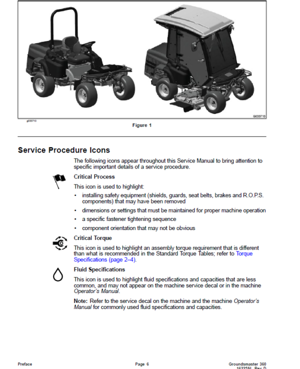
- Preface
- Service Procedure Icons
- Table of Contents
- Chapter 1 : Safety
- Safety Instructions
- Supervisor’s Responsibilities
- Before Operating the Machine
- While Operating the Machine
- Maintenance and Service
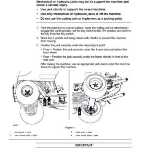
- Jacking Instructions
- Raising the Front of the Machine
- Raising the Rear of the Machine
- Safety and Instructional Decals
- Chapter 2 : Specifications and Maintenance
- Specifications
- Decimal and Millimeter Equivalents
- U.S. to Metric Conversions
- Torque Specifications
- Identifying the Fastener
- Calculating the Torque Values When Using a Drive-Adapter Wrench
- Standard Torque for Dry, Zinc Plated, and Steel Fasteners (Inch Series)
- Standard Torque for Dry, Zinc Plated, and Steel Fasteners (Metric Fasteners)
- Other Torque Specifications
- Conversion Factors
- Shop Supplies
- Special Tools
- Chapter 3 : Diesel Engine
- 1 Specifications
- Engine
- General Information
- Traction Unit Operator’s Manual
- Yanmar Engine Service and Troubleshooting Manuals
- Engine Electronic Control Unit (ECU)
- Yanmar Engine
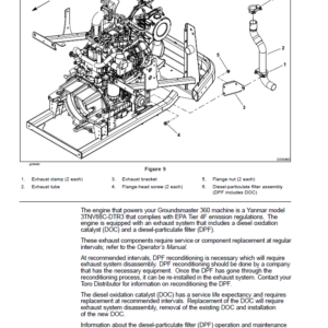
- Diesel Particulate Filter (DPF)
- Service and Repairs
- Air Cleaner System
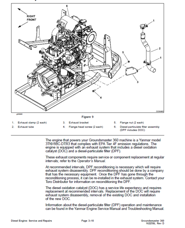
- Exhaust System
- Radiator
- Fuel System
- Engine
- Yanmar TNV (Tier 4) Series Service Repair Manual
- Yanmar TNV (Tier 4) Series Troubleshooting Manual
- Chapter 4 : Hydraulic System
- 1 Specifications
- Hydraulic System
- General Information
- Pushing the Traction Unit
- Releasing Pressure from the Hydraulic System
- Traction Circuit Component Failure
- Hydraulic Hoses
- Installing the Hydraulic Hose and Tube (O-Ring Face Seal Fitting)
- Installing the Hydraulic Fittings (SAE Straight Thread O-Ring Fitting into the Component Port)
- Hydraulic Schematics
- Hydraulic Flow Diagrams
- Traction Circuits
- Steering Circuit
- Lift, Lower Circuit: Raise
- Lift, Lower Circuit: Lower
- PTO Circuit
- Special Tools
- Hydraulic Pressure Testing Kit
- 15 GPM Hydraulic Tester Kit (Pressure and Flow)
- 40 GPM Hydraulic Tester (Pressure and Flow)
- Hydraulic Hose Kit
- O-Ring Kit
- High Flow Hydraulic Filter Kit
- Hydraulic Test Fitting Kit
- Wheel Hub Puller
- Remote Starter Switch
- Troubleshooting
- General Hydraulic System Problems
- Traction Circuit Problems
- PTO Circuit Problems
- Steering and Lift, Lower Circuit Problems
- Testing the Hydraulic System
- Testing the Traction System Operation
- Testing the Charge Relief Valve Pressure (Using Pressure Gauge)
- Testing the Traction Relief Valve Pressure (Using Pressure Gauge)
- Testing the Transmission Piston Pump Flow (Using Tester with Pressure Gauges and Flow Meter)
- Testing the Rear Wheel Motor Efficiency (Using Tester with Pressure Gauges and Flow Meter)
- Testing the PTO Pressure Valve (Using Pressure Gauge)
- Testing the Implement Relief Pressure (Using Pressure Gauge)
- Testing the Gear Pump Flow (Using Tester with Pressure Gauges and Flow Meter)
- Testing the Lift Cylinder for Internal Leakage
- Service and Repairs
- General Precautions for Removing and Installing the Hydraulic System Components
- Checking the Hydraulic Lines and Hoses
- Priming the Hydraulic Pumps
- Flushing the Hydraulic System
- Filtering the Closed-Loop Traction Circuit
- Charging the Hydraulic System
- Hydraulic Tank
- Rear Wheel Motors
- Front Wheel Motors
- Servicing the Wheel Motor
- Traction Linkage Assembly
- Transmission
- Servicing the Transmission
- CrossTrax Traction Manifold Assembly
- Servicing the CrossTrax Traction Manifold Assembly
- Servicing the Cartridge Valves in a Control Manifold
- Gear Pump
- Servicing the Gear Pump
- Steering Control Valve
- Servicing the Steering Control Valve
- Steering Cylinder
- Servicing the Steering Cylinder
- Steering Selector Manifold Assembly
- Servicing the Steering Selector Manifold Assembly
- Deck Lift Manifold Assembly
- Servicing the Deck Lift Manifold Assembly
- Lift Cylinder
- Servicing the Lift Cylinder
- Quick Attach System (QAS) Control Manifolds (Optional Kit)
- Servicing the Quick Attach System (QAS) Control Manifolds (Optional Kit)
- Oil Cooler
- Parker Torqmotor™ Service Procedure (TC, TB, TE, TJ, TF, TG, TH and TL Series)
- Eaton Parts and Repair Information: 5 Series Steering Control Units
- Chapter 5 : Electrical System
- General Information
- Electrical Schematics and Diagrams
- Toro Electronic Controller (TEC)
- Yanmar Engine Electronic Control Unit (ECU)
- Yanmar Engine Electrical Components
- CAN-bus Communications
- Special Tools
- Multimeter
- Terminal Protector
- Battery Hydrometer
- Dielectric Gel
- InfoCenter Display
- Splash Screen
- Main Information Screen
- Operator Advisory Screen
- Main Menu Screen
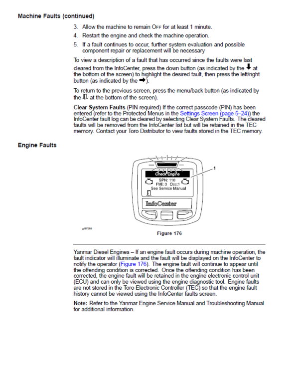
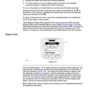
- Faults Screen
- Service Screen
- Diagnostics Screen
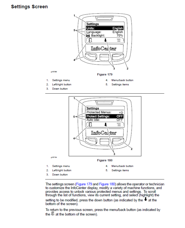
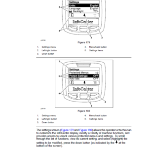
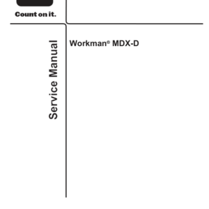
- Settings Screen
- About Screen
- Troubleshooting
- Operator Advisories
- Using the InfoCenter Display for Troubleshooting
- Fault Codes
- TEC Logic Chart
- Starting Problems
- General Run and Transport Problems
- Cutting Deck Operating Problems
- 4-Wheel Steer Operating Problems
- Electrical System Quick Checks
- Testing the Battery (Open Circuit Test)
- Testing the Charging System
- Testing the Glow Plug System
- Checking the Operation of the Interlock Switches
- Adjustments
- Traction Neutral Sensor
- Parking Brake Sensor
- Steering Home Sensor
- Testing the Electrical Components
- Fusible Link Harness
- Fuses
- Operator Cab Fuses (Machines with Operator Cab)
- Toro Electronic Controller (TEC)
- Key Switch
- PTO Switch
- Deck Lift Switch
- Steering Selector Switch
- Engine Speed Switch
- Seat Switch
- Windshield Washer, Wiper Switch (Machines with Operator Cab)
- Air Conditioning Switch (Machines with Operator Cab)
- Fan Speed Switch (Machines with Operator Cab)
- Work Light Switch (Machines with Operator Cab–Optional)
- Traction Neutral Sensor
- Parking Brake Sensor
- Steering Home Sensor
- Relays with 4 Terminals
- Relays with 5 Terminals
- PTO Solenoid Valve Coil
- Hydraulic Solenoid Valve Coils
- Fuel Pump
- CAN-bus Terminator Resistor
- Resistor Assemblies
- Diode Assemblies
- Fan Speed Switch (Machines with Two−Post ROPS Extension Operator Fan Kit)
- Resistor Module (Machines with Two−Post ROPS Extension Operator Fan Kit)
- Service and Repairs
- PTO Solenoid Valve Coil
- Hydraulic Solenoid Valve Coils
- Battery Storage
- Battery Care
- Servicing the Battery
- Chapter 6 : Chassis
- 1 Specifications
- Chassis
- General Information
- Special Tools
- Wheel Hub Puller
- Steering Alignment Tools
- Adjustments
- Adjusting the Brake
- Aligning the Wheels
- Service and Repairs
- Wheels
- Servicing the Brake
- Brake Cables
- Rear Steering Fork
- Front Steering Fork
- Front Steering Assembly
- Rear Steering Assembly
- Servicing the Steering Assembly Bushings
- Frame Assembly
- Steering Column
- PTO Driveshaft
- Servicing the PTO Driveshaft Cross and Bearing
- Cutting Deck Lift Assembly
- Control Console
- Power Center Assembly (Machines without Operator Cab)
- Power Center Assembly (Machines with Operator Cab)
- Operator Seat
- Servicing the Operator Seat (Machines without Operator Cab)
- Servicing the Operator Seat (Machines with Operator Cab)
- Hood
- Chapter 7 : Cutting Deck
- General Information
- Specifications
- Cutting Deck Operator's Manual
- Factors That Can Affect Cutting Performance
- Service and Repairs
- Blade Stopping Time
- Cutting Deck
- Idler Assembly
- Blade Spindle
- Servicing the Blade Spindle
- Gearbox
- Cutting Deck Pull Links
- Chapter 8 : Operator Cab
- General Information
- Traction Unit Operator’s Manual
- Electrical Components and Schematic
- Air Conditioning System
- Cab Heater System
- Air Conditioning System Performance
- Service and Repairs
- General Precautions for Removing and Installing the Air Conditioning System Components
- Air Conditioning Compressor
- Roof Assembly
- Heating and Air Conditioning Components
- Air Conditioning Condenser Fan Assembly
- Air Conditioning Condenser Assembly
- Mixing Box Assembly
- Heater and Air Conditioning Evaporator Cores
- Blower Fan
- Windshield Wiper Assembly
- Valeo Compressor Service Repair Manual
- Appendix A: Foldout Drawings
- Hydraulic Schematic
- Electrical Schematic – Platform
- Electrical Schematic – Engine
- Electrical Schematic – Cab (page 1 of 2)
- Electrical Schematic – Cab (page 2 of 2)
- Electrical Schematic – Attachments
- Electrical Schematic – Debris Collection
- Wire Harness Drawing – Platform
- Wire Harness Diagram – Platform
- Wire Harness Drawing – Engine
- Wire Harness Diagram – Engine
- Wire Harness Drawing – Cab Power
- Wire Harness Diagram – Cab Power
- Wire Harness Drawing – Cab Headliner
- Wire Harness Diagram – Cab Headliner
- Wire Harness Drawing – Attachments
- Wire Harness Diagram – Attachments
- Wire Harness Drawing and Diagram – Debris Collection
- Wire Harness Drawing and Diagram – EU Light Kit Model 30690 (No Cab)
- Wire Harness Drawing and Diagram – EU Light Kit Model 30640 (Cab)
- Wire Harness Diagram − Two−Post ROPS Extension (sheet 1 of 2)
- Wire Harness Diagram − Two−Post ROPS Extension (sheet 2 of 2)
- Electrical Drawing Designations
Be the first to review “Toro Groundsmaster 360 (4-Wheel Drive Models with Yanmar Engines) Service Repair Manual”
You must be logged in to post a review.
Reviews
There are no reviews yet.