 Service Repair Manual")
Toro Groundsmaster 3500-D (Model 30821, 30839, 30843) Service Repair Manual
$30.00
Manual Included:
- Service Repair Manual: 266 Pages
Specifications:
- Brand: Toro
- Model: Groundsmaster 3500-D (Model 30821, 30839, 30843)
- Type: Rotary Mowers
- Manuals: Service Repair Manual
- Publication Numbers: 01088SL
- Language: English
- Format: PDF
- Description
- Reviews (0)
Description
Table of Content – Groundsmaster 3500-D (Model 30821, 30839, 30843)
- Title Page
- Revision History
- Reader Comments
- Preface
- Table Of Contents
- 1 – Safety
- General Safety Instructions
- Before Operating
- While Operating
- Maintenance and Service
- Jacking Instructions
- Safety and Instruction Decals
- 2 – Product Records and Maintenance
- Product Records
- Maintenance
- Equivalents and Conversions
- Torque Specifications
- Lubrication
- Preparation for Seasonal Storage
- 3 – Kubota Diesel Engine
- Introduction
- Specifications
- Adjustments
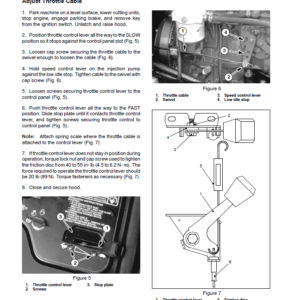
- Adjust Throttle Cable
- Service and Repairs
- Replace Traction Belt
- Bleed Fuel System
- Bleed Air from Fuel Injectors
- Muffler and Air Cleaner
- Fuel System
- Radiator (SN Below 313999999)
- Radiator and Oil Cooler Assembly (SN Above 314000000)
- Engine
- Kubota 05 Series Workshop Manual (S.N Below 250000000)
- Kubota 05 E2B Series Workshop Manual (S.N 250000001-270999999)
- Kubota 05 E3B Series Workshop Manual (S.N 280000001 & up)
- 4 – Hydraulic System
- Specifications
- General Information
- Traction Unit Operator’s Manual
- Check Hydraulic Fluid
- Towing Traction Unit
- Hydraulic Hoses
- Hydraulic Hose and Tube Installation
- Hydraulic Fitting Installation
- Relieving Hydraulic System Pressure
- Traction Circuit (Closed Loop) Component Failure
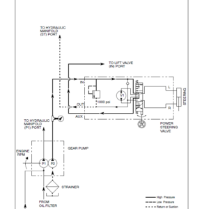
- Hydraulic Schematics
- SN Below 240000600
- SN 240000601 to 313999999
- SN Above 314000000
- Hydraulic Flow Diagrams
- Traction Circuits
- Cutting Unit Circuit
- Lift Circuit (Up)
- Lift Circuit (Down)
- Sidewinder Circuit
- Steering Circuit
- Special Tools
- Troubleshooting
- Testing
- Before Performing Hydraulic Tests
- Traction Circuit Working Pressure Test (Using Pressure Gauge)
- Piston Pump (P3) Flow and Traction Relief Pressure Test (Using Tester with Pressure
- Charge Relief Valve Pressure Test
- Gear Pump (P2) Flow Test (Using Tester with Pressure Gauges and Flow Meter)
- Wheel Motor Efficiency Test (Using Tester with Pressure Gauges and Flow Meter)
- Cutting Deck Circuit Pressure Test
- Gear Pump (P1) Flow Test (Using Tester with Pressure Gauges and Flow Meter)
- Manifold Relief Valve (R1) Pressure Test
- Logic (Counterbalance) Valve (LC1) Pressure Test
- Deck Motor Efficiency – Case Drain Test (Using Tester with Pressure Gauges and Flow)
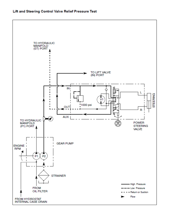
- Lift and Steering Control Valve Relief Pressure Test
- Steering Control Valve Test
- Adjustments
- Adjust Traction Drive for Neutral
- Braking Valve Adjustment
- Service and Repairs
- General Precautions for Removing and Installing Hydraulic System Components
- Change Hydraulic Fluid
- Replace Hydraulic Oil Filter
- Replace Traction Belt
- Check Hydraulic Lines and Hoses
- Flush Hydraulic System
- Filtering Closed- Loop Traction Circuit
- Charge Hydraulic System
- Hydraulic Tank and Hydraulic Oil Filter
- Oil Cooler
- Front Wheel Motors
- Rear Wheel Motor
- Wheel Motor Service
- Rotary Cutting Motors
- Rotary Cutting Motor Service (Haldex)
- Rotary Cutting Motor Service (Casappa)
- Hydraulic Manifold
- Hydraulic Manifold Service (Serial Number Below 240000600)
- Hydraulic Manifold Service (Serial Number 240000601 to 313999999)
- Hydraulic Manifold Service (Serial Numbers Above 314000000)
- Control Valve
- Control Valve Service
- Piston Pump
- Piston Pump Service
- Gear Pump
- Gear Pump Service (Serial Number Below 260000400)
- Gear Pump Service (Serial Numbers Above 260000400)
- Steering Control Valve
- Steering Control Valve Service (Serial Numbers Below 240000000)
- Steering Control Valve Service (Serial Numbers Above 240000000)
- Sidewinder
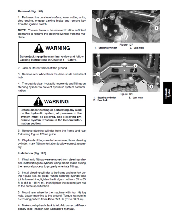
- Front Lift Cylinder
- Rear Lift Cylinder
- Lift Cylinder Service
- Steering Cylinder
- Steering Cylinder Service
- Ross Torqmotor Wheel Motor Service Repair Manual
- Eaton Piston Pump Repair Information
- Ross Hydraguide Steering Control Servcie Manual
- Danfoss Steering Control Service Repair Manual
- 5 – Electrical System
- Electrical Schematics and Diagrams
- Special Tools
- Troubleshooting
- Electrical System Quick Check
- Battery Test (Open Circuit Test)
- Charging System Test
- Glow Plug System Test
- Check Operation of Interlock Switches
- Component Testing
- Ignition Switch
- Glow Relay
- Interlock, Neutral, Seat, and High Temperature Shutdown Relays
- Hour Meter
- SRV Valve Solenoid
- Diode Assemblies
- Warning Light Cluster (Serial Numbers Below 240000000)
- Indicator Lights (Serial Numbers Above 240000000)
- Cutting Unit Drive Switch (Serial Number Below 314000000)
- Cutting Unit Drive Switch (Serial Number Above 314000000)
- Neutral Switch
- Seat Switch
- Parking Brake and Transport, Mow Switches
- Fusible Link Harness
- High Temperature Warning and Shutdown Switches
- Fuel Pump
- Fuel Stop Solenoid (Solenoid With 3 Wire Connector)
- Fuel Stop Solenoid (Solenoid With 2 Wire Connector)
- Glow Controller
- Standard Control Module
- Service and Repairs
- Battery Storage
- Battery Care
- Battery Service
- Solenoid Valve Coil
- 6 – Wheels, Brakes and Chassis
- Specifications
- Special Tools
- Adjustments
- Adjust Brake Lever
- Adjust Brakes
- Adjust Front Lift Arms
- Adjust Front Lift Arm Carrier Stop Bracket Assembly
- Adjust Rear Lift Arm
- Service and Repairs
- Standard Seat
- Deluxe Seat
- Front Wheel and Brake
- Rear Fork and Wheel
- Brake Lever Linkages
- Steering Column
- Front Lift Arms
- Rear Lift Arm
- Sidewinder Carrier
- Hood Removal
- 7 – Cutting Units
- Specifications
- Troubleshooting
- Special Tools
- Adjustments
- Height Of Cut Adjustment
- Adjust Roller Scraper
- Blade Plane Inspection and Adjustment
- Service and Repairs
- Blade Stopping Time
- Cutting Unit Removal and Installation
- Cutting Blade Removal and Installation
- Inspecting and Sharpening Blade
- Rear Roller
- Rear Roller Service (Non-Greasable Bearings)
- Rear Roller Service (Greasable Bearings)
- Rear Roller Service (Greasable Bearings with Bearing Nut)
- Front Roller Service
- Blade Spindle Service
- Carrier Frame
- 8 – Electrical Diagrams
- Serial No 90101 to 230999999)
- Schematic
- Glow Circuits
- Crank Circuits
- Run Circuits (Transport)
- Run Circuits (Mow)
- Harness Diagram (SN 90101 to 230999999)
- Harness Drawing (SN 90101 to 230999999)
- Serial No 240000001 to 314000000)
- Schematic
- (Serial Numbers 314000001 to 403440000)
- (Serial Numbers Above 403440001)
- Harness Diagram (SN 240000001 to 313999999)
- Harness Drawing (SN 240000001 to 313999999)
- Harness Diagram (SN 314000001 to 403440000)
- Harness Drawing (SN 314000001 to 403440000)
- Harness Diagram(Serial Numbers Above 403440001)
- Wire Harness Diagram(Serial Numbers Above 403430001)
Be the first to review “Toro Groundsmaster 3500-D (Model 30821, 30839, 30843) Service Repair Manual”
You must be logged in to post a review.
Reviews
There are no reviews yet.