
Toro Groundsmaster 3280-D, 3320 Service Repair Manual
$34.00
Manual Included:
- Service Repair Manual: 508 Pages
Specifications:
- Brand: Toro
- Model: Groundsmaster 3280-D, 3320
- Type: Rotary Mowers
- Manuals: Service Repair Manual
- Publication Numbers: 05138SL
- Language: English
- Format: PDF
- Description
- Reviews (0)
Description
Table of Content – Groundsmaster 3280-D, 3320
- Title Page
- Revision History
- Reader Comments
- Preface
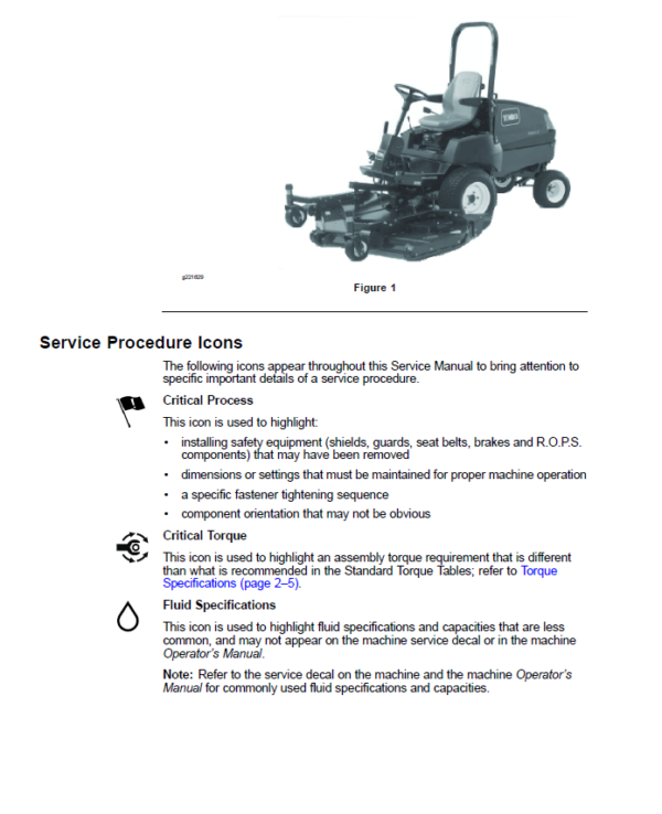
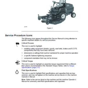
- Service Procedure Icons
- Table of Contents
- Chapter 1 : Safety
- Safety Instructions
- Supervisor’s Responsibilities
- Before Operating the Machine
- While Operating the Machine
- Before starting the machine
- Before stopping the machine
- Maintenance and Service
- Jacking Instructions
- Raising the Front of the Machine
- Raising the Rear of the Machine
- Safety and Instructional Decals
- Chapter 2 : Specifications and Maintenance
- Specifications
- Decimal and Millimeter Equivalents
- U.S. to Metric Conversions
- Torque Specifications
- Identifying the Fastener
- Fasteners with a Locking Feature
- Calculating the Torque Values When Using a Drive-Adapter Wrench
- Standard Torque for Dry, Zinc Plated, and Steel Fasteners (Inch Series)
- Standard Torque for Dry, Zinc Plated, and Steel Fasteners (Metric Fasteners)
- Other Torque Specifications
- Conversion Factors
- Shop Supplies
- Special Tools
- Hydraulic Pressure Testing Kit
- 57 LPM (15 GPM) Hydraulic Tester Kit
- 150 LPM (40 GPM) Hydraulic Tester
- Hydraulic O-Ring Kit
- Hydraulic Hose Kit
- Hydraulic Test Fitting Kit
- High Flow Hydraulic Filter Kit
- Remote Starter Switch
- Multimeter
- Battery Terminal Protector
- Chapter 3 : Gasoline Engine
- 1 Specifications
- Engine – Groundsmaster 3320-G
- General Information
- Adding Oil to Engine
- Adjustments
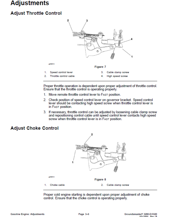
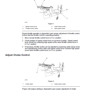
- Adjust Throttle Control
- Adjust Choke Control
- Adjust Engine Speed
- Service and Repairs
- Fuel System
- Check Fuel Lines and Connections
- Drain and Clean Fuel Tank
- Removing the Fuel Tank
- Installing the Fuel Tank
- Air Cleaner
- Removing the Air Cleaner
- Installing the Air Cleaner
- Radiator
- Removing the Radiator
- Installing the Radiator
- Engine
- Removing the Engine
- Installing the Engine
- BRIGGS AND STRATTON, DAIHATSU REPAIR MANUAL FOR 3-CYLINDER, LIQUID-COOLED,GASOLINE ENGINES
- Chapter 4 : Diesel Engine
- 1 Specifications
- Engine – Groundsmaster 3280-D
- General Information
- Traction Unit Operator’s Manual
- Engine Identification
- Kubota Engine Workshop Manuals
- Engine Group Code
- Adjustments
- Adjusting the Throttle Control
- Service and Repairs
- Air Cleaner System
- Removing the Air Cleaner System
- Installing the Air Cleaner System
- Exhaust System
- Removing the Exhaust System
- Installing the Exhaust System
- Radiator
- Removing the Radiator
- Installing the Radiator
- Fuel System
- Checking the Fuel Lines and Connections
- Draining and Cleaning the Fuel Tank
- Priming the Fuel System
- Removing the Fuel Tank
- Installing the Fuel Tank
- Engine
- Removing the Engine
- Installing the Engine
- KUBOTA 05-E2B SERIES WORKSHOP MANUAL
- KUBOTA 05-E3B SERIES WORKSHOP MANUAL
- KUBOTA 05-E4B SERIES WORKSHOP MANUAL
- Chapter 5 : Hydraulic System
- 1 Specifications
- Groundsmaster 3280-D and 3320-G
- General Information
- Checking the Hydraulic Fluid
- Pushing or Towing the Traction Unit
- Releasing Pressure from the Hydraulic System
- Releasing the Hydraulic Pressure from the Traction Circuit
- Releasing the Hydraulic Pressure from the Lift Circuit
- Releasing the Hydraulic Pressure from the Steering Circuit
- Traction Circuit Component Failure
- Hydraulic Hoses
- Installing the Hydraulic Hose and Tube (O-Ring Face Seal Fitting)
- Hose, Tube Installation Torque Table
- Flats From Wrench Resistance Table
- Installing the Hydraulic Fittings (SAE Straight Thread O-Ring Fitting into the Component Port)
- Installing the Non-Adjustable Fittings
- Fitting Installation Torque Table
- Flat From Finger Tight Table
- Installing an Adjustable Fitting
- Flat From Finger Tight Table
- Hydraulic Schematics
- Hydraulic Flow Diagrams
- Traction Circuit (Machine Serial Number below 316000000)
- Forward Direction
- Reverse Direction
- Traction Circuit (Machine Serial Number above 316000000)
- Forward Direction
- Reverse Direction
- Lift Circuit (Machine Serial Number below 311000000)
- Raise Cutting Deck (or Implement)
- Lower Cutting Deck (or Implement)
- Counterbalance
- Lift Circuit (Machine Serial Number above 311000000)
- Raise the Cutting Deck (or Implement)
- Lower the Cutting Deck (or Implement)
- Steering Circuit (Machine Serial Number below 316000000)
- Left Turn
- Right Turn
- Steering Circuit (Machine Serial Number above 316000000)
- Left Turn
- Right Turn
- Special Tools
- Hydraulic Pressure Testing Kit
- 15 GPM Hydraulic Tester Kit (Pressure and Flow)
- 40 GPM Hydraulic Tester (Pressure and Flow)
- Hydraulic Hose Kit
- Hydraulic Test Fitting Kit
- O-Ring Kit
- High Flow Hydraulic Filter Kit
- Remote Starter Switch
- Troubleshooting
- General Hydraulic System Problems
- Traction Circuit Problems
- Lift, Lower Circuit Problems
- Steering Circuit Problems
- Testing the Hydraulic System
- Charge Pressure Test (Using Pressure Gauge) (Machine Serial Numbers below 316000000)
- Implement Relief Pressure Test (Using Pressure Gauge) (Machine Serial Numbers below 316000000)
- Lift Cylinder Internal Leakage Test (Machine Serial Numbers below 316000000)
- Test Procedure
- Steering Cylinder Internal Leakage Test (Machine Serial Numbers below 316000000)
- Test Procedure
- Charge Pump Flow Test (Using Tester With Pressure Gauges and Flow Meter) (Machine Serial Numbers below 316000000)
- Testing the Traction Circuit–Charge Pressure (Machine Serial Numbers above 316000000)
- Test Procedure
- Testing the Traction Circuit–Hydraulic Pump Flow and Relief Pressure (Machine Serial Numbers above 316000000)
- Test Procedure
- Testing the Steering Circuit–Steering Control Valve, Relief Valve Pressure, and Steering Cylinder (Machine Serial Numbers above 316000000)
- Test Procedure
- Testing the Steering Circuit–Charge Pump Flow (Machine Serial Numbers above 316000000)
- Test Procedure
- Testing the Lift Circuit–Lift Cylinder Internal Leakage (Machine Serial Numbers above 316000000)
- Test Procedure
- Adjustments
- Traction Pedal Friction Wheel (Machine Serial Number below 316000000)
- Adjusting the Traction Pedal Friction Wheel
- Service and Repairs
- General Precautions for Removing and Installing the Hydraulic System Components
- Before Repairing or Replacing the Components
- After Repairing or Replacing the Components
- Checking the Hydraulic Lines and Hoses
- Priming the Hydraulic Pump
- Flushing the Hydraulic System
- Filtering the Closed-Loop Traction Circuit (Machine Serial Number above 316000000)
- Charging the Hydraulic System
- Transmission Driveshaft (Machine Serial Numbers below 316000000)
- Removing the Transmission Driveshaft
- Aligning the Transmission Driveshaft
- Installing the Transmission Driveshaft
- Hydrostatic Transmission (Machine Serial Numbers below 316000000)
- Removing the Hydrostatic Transmission
- Installing the Hydrostatic Transmission
- Servicing the Hydrostatic Transmission (Machine Serial Numbers below 316000000)
- Hydrostatic Transmission Neutral Arm Assembly (Machine Serial Number below 316000000)
- Disassembling the Hydrostatic Transmission Neutral Arm Assembly
- Assembling the Hydrostatic Transmission Neutral Arm Assembly
- Hydraulic Pump Driveshaft (Machine Serial Number above 316000000)
- Removing the Hydraulic Pump Driveshaft
- Servicing the Driveshaft Cross and Bearing
- Installing the Hydraulic Pump Driveshaft
- Hydraulic Pump (Machine Serial Number above 316000000)
- Removing the Hydraulic Pump
- Installing the Hydraulic Pump
- Servicing the Hydraulic Pump (Machine Serial Number above 316000000)
- Traction Neutral Arm Assembly (Machine Serial Number above 316000000)
- Disassembling the Traction Neutral Arm Assembly
- Assembling the Traction Neutral Arm Assembly
- Front Axle Drive Motor (Machine Serial Number above 316000000)
- Removing the Front Axle Drive Motor
- Installing the Front Axle Drive Motor
- Servicing the Front Axle Drive Motor (Machine Serial Number above 316000000)
- Lift Cylinder
- Removing the Lift Cylinder
- Installing the Lift Cylinder
- Steering Control Valve
- Removing the Steering Control Valve
- Installing the Steering Control Valve
- Servicing the Steering Control Valve
- Steering Cylinder (2-Wheel Drive)
- Removing the Steering Cylinder (2-Wheel Drive)
- Installing the Steering Cylinder (2-Wheel Drive)
- Servicing the Steering Cylinder (2-Wheel Drive)
- Disassembling the Steering Cylinder (2-Wheel Drive)
- Inspecting the Steering Cylinder
- Assembling the Steering Cylinder (2-Wheel Drive)
- Steering Cylinder (4-Wheel Drive)
- Removing the Steering Cylinder (4-Wheel Drive)
- Installing the Steering Cylinder (4-Wheel Drive)
- Servicing the Steering Cylinder (4-Wheel Drive)
- Disassembling the Steering Cylinder (4-Wheel Drive)
- Inspecting the Steering Cylinder
- Assembling the Steering Cylinder (4-Wheel Drive)
- Lift Control Valve (Machine Serial Numbers below 316000000)
- Removing the Lift Control Valve
- Installing the Lift Control Valve
- Servicing the Lift Control Valve (Machine Serial Numbers below 311000000)
- Disassembly the Lift Control Valve
- Inspecting the Lift Control Valve
- Assembling the Lift Control Valve
- Counterbalance Valve Manifold (Machine Serial Numbers below 311000000) (If Equipped)
- Removing the Counterbalance Valve Manifold
- Servicing the Manifold
- Installing the Counterbalance Valve Manifold
- Lift Control Valve (Machine Serial Number above 311000000)
- Removing the Lift Control Valve
- Installing the Lift Control Valve
- Servicing the Lift Control Valve (Machine Serial Number above 311000000)
- Servicing the Control Manifold Cartridge Valve
- Oil Cooler (Groundsmaster 3280-D)
- Removing the Oil Cooler
- Inspecting the Oil Cooler
- Installing the Oil Cooler
- DANFOSS DDC20 AXIAL PISTON PUMP SERVICE MANUAL
- DANFOSS SERIES 15 AXIAL PISTON PUMPS, MOTORS AND TRANSMISSIONS REPAIR MANUAL
- DANFOSS SERIES 15 AXIAL PISTON PUMPS, MOTORS AND TRANSMISSIONS SERVICE MANUAL
- EATON MODEL 74111 AND 74118 FIXED AXIAL PISTON MOTOR REPAIR INFORMATION
- DANFOSS STEERING UNIT TYPE OSPM SERVICE MANUAL
- Chapter 6 : Electrical System
- General Information
- Electrical Schematics and Wire Harness Drawings, Diagrams
- Standard Control Module (SCM)
- SCM Inputs
- SCM Outputs
- Standard Control Module Logic Chart
- Special Tools
- Multimeter
- Terminal Protector
- Battery Hydrometer
- Dielectric Gel
- Troubleshooting
- Starting Problems
- General Run and Transport Problems
- Cutting Deck Operating Problems
- Cutting Deck Lift, Lower Problems
- Electrical System Quick Checks
- Testing the Battery (Open Circuit Test)
- Battery Test Table
- Testing the Charging System
- Battery Voltage Table
- Testing the Glow Plug System (Groundsmaster 3280-D)
- Checking the Operation of the Interlock Switches
- Adjustments
- Traction Neutral Sensor (Machine Serial Number above 316000000)
- Adjusting the Traction Neutral Sensor
- Parking Brake Switch
- Adjusting the Parking Brake Switch
- Testing the Electrical Components
- Fusible Link Harness
- Testing the Fusible Link Harness
- Fuses (Machine Serial Number below 400000000)
- Identification and Function
- Testing the Fuses
- Fuses (Machine Serial Number above 400000000)
- Identification and Function
- Testing the Fuses
- Operator Cab Fuses (Machines with Operator Cab)
- Identification and Function
- Testing the Fuses
- Key Switch
- Testing the Key Switch
- Circuit Logic Table
- Indicator Lights
- Charge Indicator Light
- Engine Oil Pressure Light
- High Temperature Warning Light
- Glow Plug Indicator Light
- Testing the Indicator Lights
- Hour Meter
- Testing the Hour Meter
- PTO Switch
- Testing the PTO Switch
- Circuit Logic Table
- Deck Lift Switch (Machine Serial Numbers above 311000000)
- Testing the Deck Lift Switch
- Circuit Logic Table
- Seat Switch
- Testing the Seat Switch
- Windshield Washer, Wiper Switch (Machines with Operator Cab)
- Testing the Windshield Washer, Wiper Switch
- Circuit Logic Table
- Accessory Power Switch (Machines with Operator Cab)
- Testing the Accessory Power Switch
- Circuit Logic Table
- Fan Speed Switch (Machines with Operator Cab)
- Testing the Fan Speed Switch
- Circuit Logic Table
- Work Light Switch (Machines with Operator Cab–Optional)
- Testing the Work Light Switch
- Circuit Logic Table
- Traction Neutral Switch (Machine Serial Numbers below 316000000)
- Testing the Traction Neutral Switch
- Adjusting the Traction Neutral Switch
- Traction Neutral Sensor (Machine Serial Number above 316000000)
- Testing the Traction Neutral Sensor
- Parking Brake Switch
- Testing the Parking Brake Switch
- High Temperature Warning Switch
- Testing the High Temperature Warning Switch
- High Temperature Shutdown Switch
- Testing the High Temperature Shutdown Switch
- Engine Oil Pressure Switch
- Testing the Engine Oil Pressure Switch
- Relays (Groundsmaster 3280-D)
- Testing the Relays
- Lift Control Valve Solenoid Valve Coil (Machine Serial Number above 311000000)
- Testing the Lift Control Valve Solenoid Valve Coil
- Solenoid Valve Coil Specifications Table
- PTO Electric Clutch
- Testing the PTO Electric Clutch
- Fuel Stop Solenoid (Groundsmaster 3280-D)
- Testing the Fuel Stop Solenoid (In Place)
- Testing the Fuel Stop Solenoid (Live)
- Glow Controller (Groundsmaster 3280-D)
- Controller Operation
- Controller Checks
- Fuel Pump (Groundsmaster 3280-D)
- Testing the Fuel Pump Capacity
- Fuel Pump Specifications (for Models 30344 and 30345)
- Fuel Pump Specifications (except Models 30344 and 30345)
- Fuel Pump (Groundsmaster 3320)
- Testing the Fuel Pump Capacity
- Fuel Pump Specifications
- Fuel Pump Relay (Groundsmaster 3320)
- Testing the Fuel Pump Relay
- Service and Repairs
- Lift Control Valve Solenoid Valve Coils (Machine Serial Number above 311000000)
- Removing the Lift Control Valve Solenoid Valve Coils
- Installing the Lift Control Valve Solenoid Valve Coils
- PTO Electric Clutch
- Removing the PTO Electric Clutch
- Installing the PTO Electric Clutch
- Battery Storage
- Battery Care
- Servicing the Battery
- Battery Specifications
- Removing and Installing the Battery
- Inspecting, Maintaining, and Testing the Battery
- Cell Specific Gravity Example
- Minimum Voltage Table
- Charging the Battery
- Battery Charge Level Table
- Chapter 7 : Chassis
- Specifications
- NO TITLE
- General Information
- Service and Repairs
- Wheels
- Removing the Wheel
- Installing the Wheel
- Steering Column
- Removing the Steering Column
- Installing the Steering Column
- Rear Frame and Axle Assembly
- Removing the Rear Frame and Axle Assembly
- Installing the Rear Frame and Axle Assembly
- Rear Axle (2-Wheel Drive)
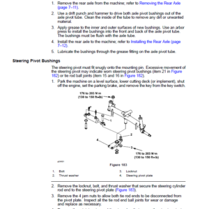
- Removing the Rear Axle
- Installing the Rear Axle
- Servicing the Rear Axle (2-Wheel Drive)
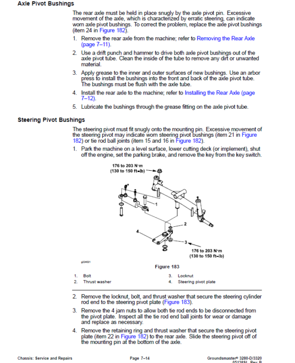
- Axle Pivot Bushings
- Steering Pivot Bushings
- Rear Axle Spindle Bushings
- Rear Wheel Bearings (2-Wheel Drive)
- Disassembling the Rear Wheel Bearings
- Assembling the Rear Wheel Bearings
- Operator Seat
- Removing the Operator Seat
- Installing the Operator Seat
- Mechanical Seat Suspension
- Removing the Mechanical Seat Suspension
- Installing the Mechanical Seat Suspension
- Pneumatic Seat Suspension
- Removing the Pneumatic Seat Suspension
- Installing the Pneumatic Seat Suspension
- Lift Arms
- Removing the Lift Arms
- Installing the Lift Arms
- Chapter 8 : Drive Axles
- Specifications
- NO TITLE
- General Information
- Front Axle
- 4-Wheel Drive Rear Axle
- Special Tools
- Differential Gear Holder
- Service and Repairs
- Servicing the Brake
- Disassembling the Brake
- Assembling the Brake
- Front Axle Shafts and Bearings
- Disassembling the Front Axle Shafts and Bearings
- Assembling the Front Axle Shafts and Bearings
- Front Axle (Machine Serial Number before 316000000)
- Removing the Front Axle
- Installing the Front Axle
- Front Axle (Machine Serial Number after 316000000)
- Removing the Front Axle
- Installing the Front Axle
- Servicing the Front Axle
- Disassembling the Front Axle
- Assembling the Front Axle
- Ring to Pinion Gear Engagement (Front Axle)
- Gear Pattern Movement Summary
- Rear Axle Driveshaft (4-Wheel Drive)
- Removing the Rear Axle Driveshaft (4-Wheel Drive)
- Installing the Rear Axle Driveshaft (4-Wheel Drive)
- Servicing the Rear Axle Driveshaft Cross and Bearing (4-Wheel Drive)
- Rear Axle (4-Wheel Drive)
- Removing the Rear Axle (4-Wheel Drive)
- Installing the Rear Axle (4-Wheel Drive)
- Bevel Gear Case and Axle Case (4-Wheel Drive Axle)
- Removing the Bevel Gear Case and Axle Case (4-Wheel Drive Axle)
- Inspecting the Bevel Gear Case and Axle Case
- Installing the Bevel Gear Case and Axle Case (4-Wheel Drive Axle)
- Differential Shafts (4-Wheel Drive Axle)
- Removing the Differential Shaft (4-Wheel Drive Axle)
- Installing the Differential Shaft (4-Wheel Drive Axle)
- Axle Shafts (4-Wheel Drive Axle)
- Removing the Axle Shaft (4-Wheel Drive Axle)
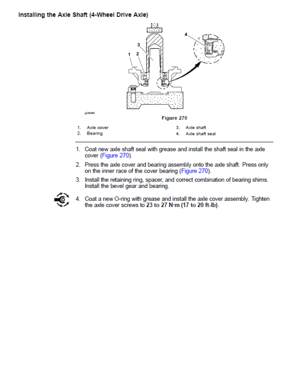
- Installing the Axle Shaft (4-Wheel Drive Axle)
- Input Shaft, Pinion Gear (4-Wheel Drive Axle)
- Removing the Input Shaft, Pinion Gear (4-Wheel Drive Axle)
- Installing the Input Shaft, Pinion Gear (4-Wheel Drive Axle)
- Differential Gear Assembly (4-Wheel Drive Axle)
- Removing the Differential Gear Assembly (4-Wheel Drive Axle)
- Inspecting the Differential Gear Assembly
- Installing the Differential Gear Assembly (4-Wheel Drive Axle)
- Pinion Gear to Ring Gear Engagement (4-Wheel Drive Axle)
- Gear Pattern Movement Summary
- Bi-Directional Clutch (4-Wheel Drive)
- Removing the Bi-Directional Clutch (4-Wheel Drive)
- Installing the Bi-Directional Clutch (4-Wheel Drive)
- Servicing the Bi-Directional Clutch (4-Wheel Drive)
- Disassembling the Bi-Directional Clutch (4-Wheel Drive)
- Assembling the Bi-Directional Clutch (4-Wheel Drive)
- Chapter 9 : PTO System
- General Information
- Service and Repairs
- PTO Drive Belt
- PTO Driveshaft
- Removing the PTO Driveshaft
- Installing the PTO Driveshaft
- Servicing the PTO Driveshaft Cross and Bearing
- PTO Shaft
- Removing the PTO Shaft
- Installing the PTO Shaft
- Aligning the PTO Pulley to the Electric Clutch Pulley
- Checking the Pulley Alignment
- Adjusting the Pulley Alignment
- Chapter 10 : Cutting Units
- General Information
- Specifications
- Cutting Unit Operator's Manual
- Troubleshooting
- Factors That Can Affect Quality of Cut
- Adjustments
- Castor Wheel Tire Pressure
- Service and Repairs
- Cutting Deck
- Idler Assembly
- Removing the Idler Assembly
- Installing the Idler Assembly
- Blade Spindle
- Removing the Blade Spindle
- Installing the Blade Spindle
- Servicing the Blade Spindle
- Disassembling the Blade Spindle
- Assembling the Blade Spindle
- Gearbox
- Removing the Gearbox
- Installing the Gearbox
- Castor Forks and Wheels
- Disassembling the Castor Forks and Wheels
- Assembling the Castor Forks and Wheels
- Cutting Deck Rollers and Skids
- Removing the Cutting Deck Rollers and Skids
- Installing the Cutting Deck Rollers and Skids
- Chapter 11 : Operator Cab
- General Information
- Operator’s Manual
- Electrical Components and Schematics
- Cab Heater System
- Service and Repairs
- Roof Assembly
- Removing the Roof Assembly
- Installing the Roof Assembly
- Heating Components
- Mixing Box Assembly
- Removing the Mixing Box Assembly
- Installing the Mixing Box Assembly
- Heater Core
- Removing the Heater Core
- Installing the Heater Core
- Blower Fan
- Removing the Blower Fan
- Installing the Blower Fan
- Windshield Wiper Assembly
- Disassembling the Windshield Wiper Assembly
- Assembling the Windshield Wiper Assembly
- Appendix A: Foldout Drawings
- Electrical Drawing Designations
- Hydraulic Schematic-3280-D (Serial Numbers below 270000400) and 3320 (Serial Numbers below 280000000)
- Hydraulic Schematic-3280-D (Serial Numbers 270000400 to 311000000) and 3320 (Serial Numbers 280000000 to 311000000)
- Hydraulic Schematic-3280-D (Serial Numbers 311000001 through 316000000)
- Hydraulic Schematic-3280-D (Machine Serial Numbers after 316000000)
- Electrical Schematic-3320
- Electrical Schematic (Machine Serial Number before 311000000)
- Electrical Schematic (Machine Serial Number 311000000 and Up)
- Electrical Schematic-Operator Cab
- Electrical Schematic-Operator Cab
- Wire Harness Drawing-Main-3320 (Serial Numbers below 260000000)
- Wire Harness Diagram-Main-3320 (Serial Numbers below 260000000)
- Wire Harness Drawing-Main-3320 (Serial Numbers above 260000000)
- Wire Harness Diagram-Main-3320 (Serial Numbers above 260000000)
- Wire Harness Drawing-Main-3280-D (Serial Numbers below 260000000)
- Wire Harness Diagram-Main-3280-D (Serial Numbers below 260000000)
- Wire Harness Drawing-Main-3280-D (Machine Serial Number 260000000 to 270000600)
- Wire Harness Diagram-Main-3280-D (Machine Serial Number 260000000 to 270000600)
- Wire Harness Drawing-Main-3280-D (Machine Serial Number 270000601 to 311000000)
- Wire Harness Diagram-Main-3280-D (Machine Serial Number 270000601 to 311000000)
- Wire Harness Drawing-Main-3280-D (Machine Serial Number 311000000 to 316000000)
- Wire Harness Diagram-Main-3280-D (Machine Serial Number 311000000 to 316000000)
- Wire Harness Drawing-Main-3280-D (Machine Serial Number 316000000 to 400000000)
- Wire Harness Diagram-Main-3280-D (Machine Serial Number 316000000 to 400000000)
- Wire Harness Drawing-Main-3280-D (Machine Serial Number 400000000 and Up)
- Wire Harness Diagram-Main-3280-D (Machine Serial Number 400000000 and Up)
- Wire Harness Drawing-Cab Model 30298 Power
- Wire Harness Diagram-Cab Model 30298 Power
- Wire Harness Drawing-Cab Model 30298 Headliner
- Wire Harness Diagram-Cab Model 30298 Headliner
- Wire Harness Drawing-Cab Model 30298 Front Mount Accessory Power Supply
- Wire Harness Diagram-Cab Model 30298 Front Mount Accessory Power Supply
- Wire Harness Drawing-Cab Model 30298 Heat, Air Conditioning Blower
- Wire Harness Diagram-Cab Model 30298 Heat, Air Conditioning Blower
- Wire Harness Drawing-Light Kit Model 30405 (Machines without Cab)
- Wire Harness Diagram-Light Kit Model 30405 (Machines without Cab)
- Wire Harness Drawing-North American Light Kit Model 30701 (Machines Serial Number 315000000 and Up)
- Wire Harness Diagram-North American Light Kit Model 30701 (Machines Serial Number 315000000 and Up)
Be the first to review “Toro Groundsmaster 3280-D, 3320 Service Repair Manual”
You must be logged in to post a review.
Reviews
There are no reviews yet.