
Hitachi ZW150-6 Wheel Loader Service Repair Manual
$35.00
Service Repair Manual (Troubleshooting) : Vol. No.TOPTC50-EN (496 Pages)
Operation Manual : Vol. No.TTPTC50-EN (527 Pages)
Workshop Manual : Vol. No.WPTC50-EN (613 Pages)
Circuit diagram: 17 Pages
- Description
- Reviews (0)
Description
Hitachi ZW150-6 Wheel Loader Service Manual
The manual is applicable for the Hitachi ZW150-6 Wheel Loader Model
Format: PDF
Language: English
Service Manual consists of the following:
For Model ZW150-6 as mentioned above:
Service Manual (Troubleshooting) : Vol. No.TOPTC50-EN (496 Pages)
Operation Manual : Vol. No.TTPTC50-EN (527 Pages)
Workshop Manual : Vol. No.WPTC50-EN (613 Pages)
Circuit diagram: 17 Pages
Table of Content of the Workshop Manual
SECTION 1 GENERAL INFORMATION
SECTION 2 MAINTENANCE STANDARD
SECTION 3 BODY
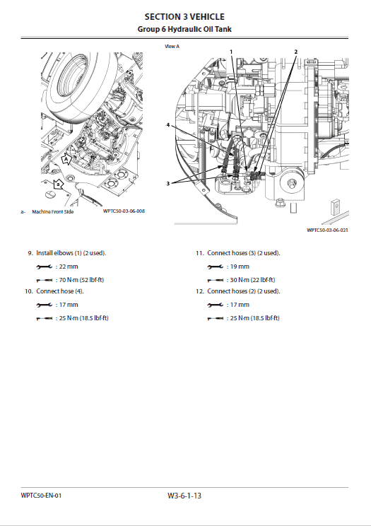
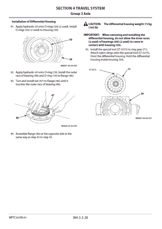
SECTION 4 TRAVEL SYSTEM
SECTION 5 ATTACHMENT
Table of Content of the Technical Manual
SECTION 4 OPERATIONAL
PERFORMANCE TEST
Group 1 Introduction
Group 2 Standard
Group 3 Engine Test
Group 4 Machine Performance Test
Group 5 Component Test
Group 6 Adjustment
SECTION 5 TROUBLESHOOTING
Group 1 Diagnosing Procedure
Group 2 Monitor
Group 3 e-Service
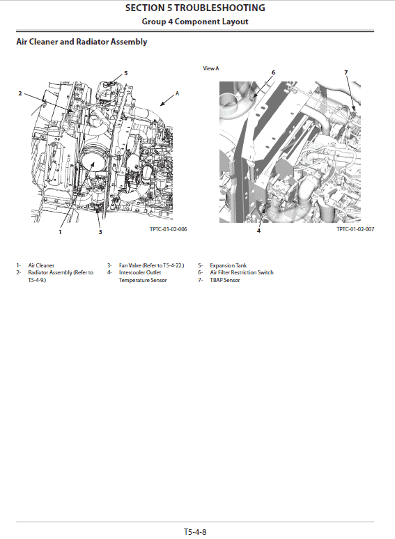
Group 4 Component Layout
Group 5 Troubleshooting A
Group 6 Troubleshooting B
Group 7 Troubleshooting C
Group 8 Air Conditioner
Table of Content of the Operation Manual
SECTION 1 GENERAL
Group 1 Specifications
Group 2 Component Layout
Group 3 Component Specifications
SECTION 2 SYSTEM
Group 1 Controller
Group 2 Control System
Group 3 ECM System
Group 4 Hydraulic System
Group 5 Electrical System
SECTION 3 COMPONENT OPERATION
Group 1 Pump Device
Group 2 Control Valve
Group 3 Cooling Fan System
Group 4 Steering Valve
Group 5 HST Motor
Group 6 Pilot Valve
Group 7 Brake Charge Valve/Manifold Valve
Group 8 Transmission
Group 9 Axle
Group 10 Brake Valve
Group 11 Priority Valve
Group 12 Ride Control Valve
Group 13 Others
Manual guide composition
Hitachi ZAXIS ZW150-6 service manual consists of the Troubleshooting and the Workshop Manual.
- Information included in the Service Manual: Technical information needed for redelivery and delivery, operation and activation of all devices and systems, operational performance tests, and troubleshooting procedures.
- Information included in the Workshop Manual: Technical information needed for maintenance and repair of the machine, tools and devices needed for maintenance and repair, maintenance standards, and removal / installation and assemble / disassemble procedures.
Reverse Rotation:
 1. When the fan reverse rotation switch is turned ON, the fan reverse rotation control solenoid valve (6) shifts by signals from the MC. (Refer to SYSTEM/Control System.)
2. Pressure oil from port P is routed to the end of the fan reverse rotation spool (2) through spool (8) of the fan reverse rotation control solenoid valve (6).
3. Therefore, fan reverse rotation spool (2) moves to the right (left on the circuit diagram).
4. Pressure oil from port P flows to the fan motor through the periphery of the fan reverse rotation spool (2) and port B.
5. Therefore, the fan rotates in reverse direction.
Be the first to review “Hitachi ZW150-6 Wheel Loader Service Repair Manual”
You must be logged in to post a review.

Reviews
There are no reviews yet.