
Linkbelt LS-1600 C2 Excavator Service Repair Manual
$38.00
Manual Included:
- Service Repair Manual: 490 pages
- Operators Manual: 120 pages
- Hydraulic and Electrical Schematics
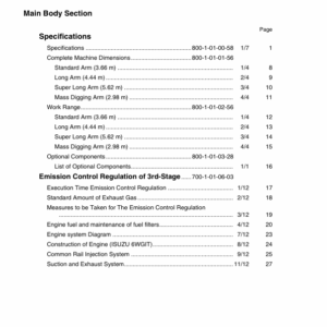
Specifications:
- Brand: LinkBelt
- Model: LS 1600 C Series II
- Type: Excavator
- Manuals: Repair and Operators Manual
- Publication Numbers: 789 and 790
- Language: English
- Format: PDF
- Description
- Reviews (0)
Description
Table of Contents (Service Manual)
1. Caution for Inspection and Maintenance
- Basic Rules
- General Rules for Disassembling
- Pre-Disassembly
- Cautions for Disassembling
- General Rules for Reassembling
- After Disassembly
- Cautions for Reassembly
- Handling of Interchangeable (Common) Parts
- Packings
- O-Ring
- Oil Seal
- Bearing
- Snap Ring
- Conversion Tables
- Length
- Area
- Volume
- Mass
- Pressure
- Torque
- Temperature
- General Rules for Disassembling
- Circuit Diagrams
- Hydraulic Circuit (For Blade)
- Hydraulic Circuit (For Offset)
- Electric Circuit
- Performance Standards
- Measuring Pressure
- Accumulator
- Hydraulic System Relief Valve Adjustment
- Main Relief Pressure
- Main Control Valve Port Relief Pressure
- Pilot Circuit Pressure
- Swing Cross Over Relief Pressure
- Points to Note for Replacement of Main Hydraulic Device
- Hydraulic Oil Pressure Release
- Hydraulic Pump
- Swing Motor
- Travel Motor
- Hydraulic Cylinder
2. Undercarriage
- Travel Device
- Removal and Installation
- Drive Sprocket
- Removal and Installation
- Take-Up Roller
- Removal and Installation
- Structural Diagram
- Tools and Jigs
- Disassembly and Reassembly
- Upper Roller
- Removal and Installation
- Structural Diagram
- Tools and Jigs
- Disassembly and Reassembly
- Lower Roller
- Removal and Installation
- Structural Diagram
- Tools and Jigs
- Disassembly and Reassembly
- Recoil Spring
- Removal and Installation
- Structural Diagram
- Disassembly and Reassembly
- Grease Cylinder
- Removal and Installation
- Structural Diagram
- Tools and Jigs
- Disassembly and Reassembly
- Track Shoe
- Removal and Installation
- Structural Diagram
- Exchange Procedure
- Rotating Joint
- Removal and Installation
3. Upper Structure
- Swing Device
- Removal and Installation
- Engine and Radiator Mounting
- Engine Installation
- Radiator Installation
- Hydraulic Pump
- Removal and Installation
- Holding Valve
- Removal and Installation
- Control Valve
- Removal and Installation
- Pilot Valve
- Removal and Installation
- Manifold Valve
- Removal and Installation
- Stack Valve
- Removal and Installation
4. Attachment
- Bucket Cylinder
- Removal and Installation
- Arm Cylinder
- Removal and Installation
- Boom Cylinder
- Removal and Installation
- Off-Set Cylinder
- Removal and Installation
- Blade Cylinder
- Removal and Installation
5. Electrical System
- Monitor System
- Outline of Monitor System
- Configuration of System
- Monitor Display Section
- Operation Indication
- Removal and Installation of Monitor Display Section
- Removal
- Disassembly and Replacement
- Installation
- Battery
6. Maintenance
- Hydraulic Pump
- Maintenance Outline
- Disassembly
- Maintenance Procedure
- Reassembly Procedure
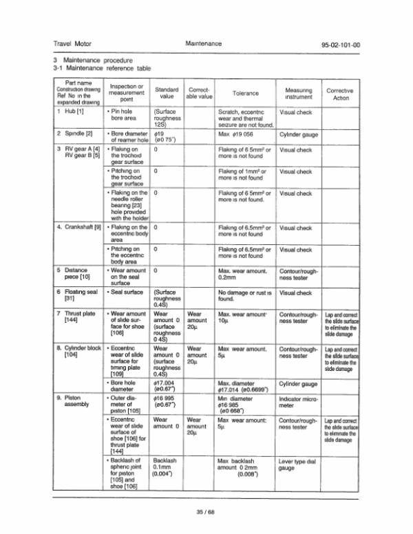
- Travel Motor
- Maintenance Outline
- Disassembly
- Maintenance Procedure
- Reassembly
- Performance Checking Test
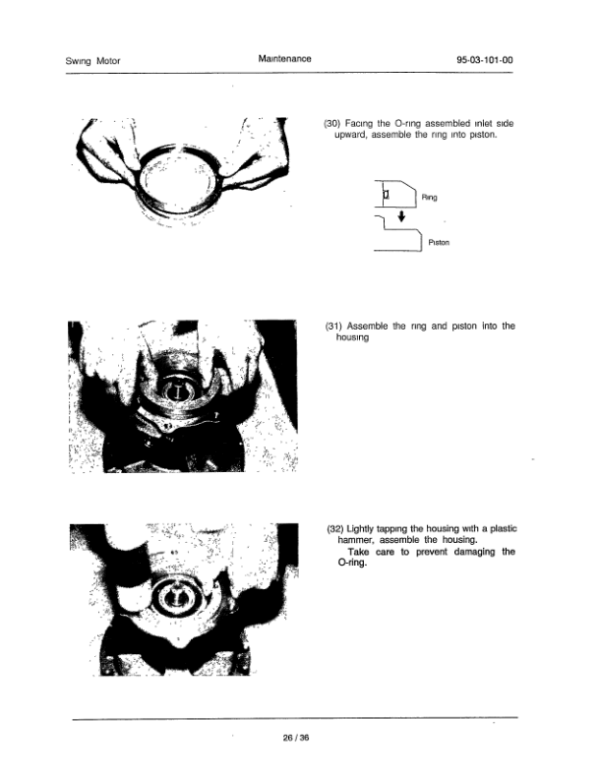
- Swing Motor
- Maintenance Outline
- Cautionary Points for Disassembly and Reassembly
- Reassembly Procedure
- Maintenance Standards
- Control Valve
- Maintenance Outline
- Disassembly
- Cleaning
- Inspection
- Assembly
- Installation
- Operation
- General Specifications of Control Valve
- Troubleshooting
- Hydraulic Cylinder
- Cylinder Construction
- Cautionary
- Maintenance
- Troubleshooting
- Storage Standard
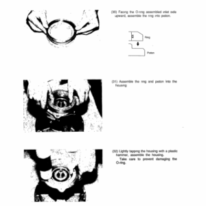
- Disassembly and Reassembly
- Pilot Valve
- Summary
- Model Code Numbers
- Specifications
- Construction
- Functions
- Actuation
- Structural Diagram
- Tools and Jigs
- Disassembly
- Maintenance Standards
- Reassembly
- Troubleshooting
- Rotating Joint
- Structural Diagram
- Tools and Jigs
- Tightening Torques for Bolts
- Disassembling Procedure
- Reassembling Procedure
- Holding Valve
- Maintenance Outline
- Adjustment of Relief Valve
- Disassembling Procedure
- Assembling Procedure
- Manifold Valve
- Maintenance Outline
- Adjustment of Relief Valve
- Disassembling Procedure
- Assembling Procedure
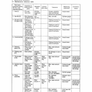
7. Maintenance Standards
- Drive Sprocket
- Take-Up Roller
- Upper Roller
- Lower Roller
- Track Shoe
- Turnable Bearing and Pinion
- Attachment Clearance Adjusting Shims
- Weight of Components
- Tightening Torque Table
Be the first to review “Linkbelt LS-1600 C2 Excavator Service Repair Manual”
You must be logged in to post a review.

Reviews
There are no reviews yet.