 Excavator Service Repair Manual")
Linkbelt 800LX (Tier 3) Excavator Service Repair Manual
$47.00
Manual Included:
- Service Repair Manual: 778 pages
- Operators Manual: 232 pages
- Parts Catalog: 509 pages
- Hydraulic and Electrical Schematics
Specifications:
- Brand: LinkBelt
- Model: 800LX Tier 3 (800Q3)
- Serial Number: 6001 and up
- Type: Excavator
- Manuals: Repair and Operators Manual
- Publication Numbers: 1129
- Language: English
- Format: PDF
- Description
- Reviews (0)
Description
Table of Contents
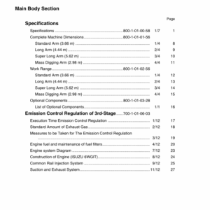
1. Specifications
- Major Equipment Specifications
- Complete Machine Dimensions
- Standard Arm (3.66 m)
- Long Arm (4.44 m)
- Super Long Arm (5.62 m)
- Mass Digging Arm (2.98 m)
- Work Range
- Standard Arm (3.66 m)
- Long Arm (4.44 m)
- Super Long Arm (5.62 m)
- Mass Digging Arm (2.98 m)
- Optional Components
- List of Optional Components
- Complete Machine Dimensions
- Emission Control Regulation of 3rd-Stage
- Execution Time Emission Control Regulation
- Standard Amount of Exhaust Gas
- Measures to be Taken for the Emission Control Regulation
- Engine Fuel and Maintenance of Fuel Filters
- Engine System Diagram
- Construction of Engine (ISUZU 6WGIT)
- Common Rail Injection System
- Suction and Exhaust System
- Major Equipment
- Equipment
- Overall
- Operator’s Cab
- Lower Mechanism
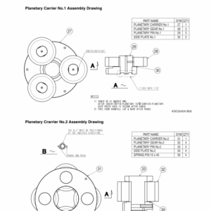
- Assembly Drawing
- Travel Unit
- Idler Wheel
- Upper Roller
- Lower Roller
- Recoil Spring
- Shoes
- Upper Mechanism
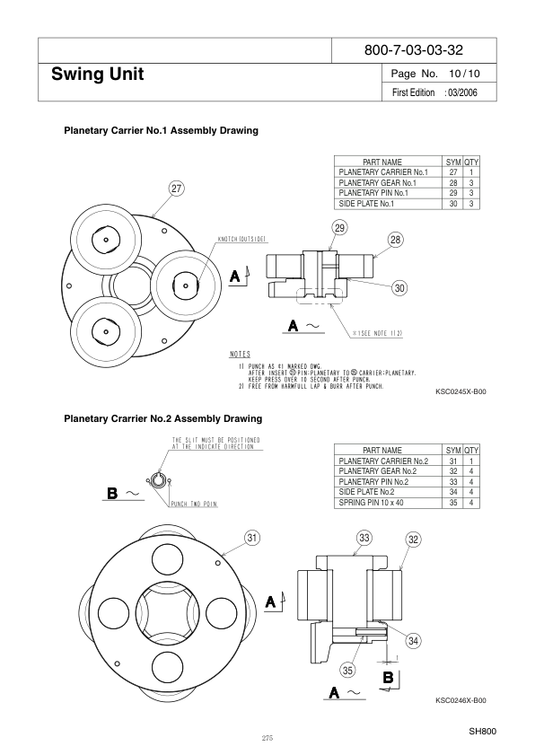
- Swing Unit
- Engine and Related Areas
- Engine
- Muffler
- Air Cleaner (With Pre-Cleaner)
- Radiator
- Fuel Tank
- Hydraulic System
- Hydraulic Pump
- Hydraulic Reservoir
- Rotating Joint
- Solenoid Valve
- Controls
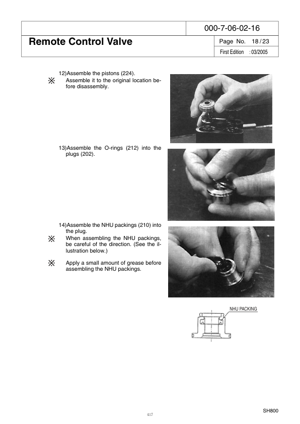
- Control Valve
- Remote Control Valve (Left/Right, Travel Operations)
- Backhoe Attachments
- Cylinder
- Attachments
- Equipment
2. Hydraulic Section
- Hydraulic Pump
- Operation Principle
- Internal Structure Drawing
- Control Valve
- Operation Explanation of Each Part
- Main Relief Valve
- Overload Relief Valve
- Foot Relief Valve
- Load Holding Valve
- Arm Regenerative
- Priority Valve
- Boom Regenerative
- Swing Unit
- Operation Principle
- Hydraulic Motor
- Anti-Cavitation Check Valve Section
- Relief Valve
- Reversal Prevention Valve
- Brake Section
- Internal Structure Drawing
- Travel Unit
- Operation Principle
- Hydraulic Motor
- Parking Brake
- 2-Speed Switch Mechanism Operation Principle
- Relief Valve
- Double Counterbalance Valve
- Fan Motor for Hydraulic Drive
- Outside Drawing
- Internal Structure Drawing
- Operation Principle
- Hydraulic Motor
- Suction Safety Valve
- Variable Flow Control Valve
- Operation of Forward/Reverse Changeover Valve
3. Hydraulic Circuits Section
- Port Locations
- Hydraulic Pump
- Control Valve
- Pilot Hose Connection Diagrams
- Pilot P&T Lines
- Pilot Control Lines
- Functional Explanation
- Functional Table
- Travel Circuits
- High Speed Travel Circuit
- Low Speed Travel Circuit
- Straight Travel Circuit
- Swing Circuits
- Swing Parking Circuit (Lever in Neutral/Swing Locked)
- Swing Parking Circuit (Brake Released)
- Swing Push Digging
- Arm Circuits
- Arm-Out Circuit
- Arm-In Load Holding
- Arm-In Circuit
- Boom Circuits
- Boom-Up Circuit (Single)
- Boom-Up Circuit (Combined)
- Boom-Down Load Holding
- Boom-Down Circuit
- Backup Circuits
- Combined Circuit (Breaker Circuit)
- Combined Circuit (High Speed Confluence Circuit)
- Other Circuits
- High Dump
- Hydraulic Circuit Diagram
4. Electric Circuits Section
- Operation Explanation
- System Chart of Functions
- Engine Control
- Work Mode Selection
- H.S.L Modes
- Auto Modes
- Load Prefetch Control
- Throttle Control
- Idling Control (Auto/One-Touch)
- Breaker Mode
- Auto Preheat (Glow Control)
- Auto Warm-Up
- Overheat Protection
- Atmospheric Pressure Compensation
- Control When Starting Engine
- Control When Stopping Engine
- Emergency Stop of the Engine
- Engine Protection Function (EPF)
- Lever Lock
- Auto Boost Control
- Swing Lock
- Swing Brake Control
- Travel Speed Switch-Over
- Travel Alarm
- Power Shut-Off Delay
- Control of Hydraulic Driven Fan
- Fuel Supply Pump Control (Automatic Stop, Optional)
- Power Transistor Protection
- Monitor Display
- Normal Display
- Message Display
- Service Support
- Summary
- Operating Instructions
- Measuring Electrical Device
- Instruments to be Measured
- Equipment for Measuring
- Measuring Methods
- Initial Controller Settings
- Verifying the Settings
- Resetting Procedures
- Setting Procedures
- List of Settings
- Error Display Functions
- Troubleshooting
- Problem Symptoms
- Inspections Prior to Troubleshooting
- Troubleshooting Procedures
- Using the Flow Chart
- Diagnosis
- Refilling Fuel
- Refilling Coolant
- Low Engine Oil Pressure
- Overheat
- Battery Charging
- Faulty Electrical System
- Electric Wiring Diagrams
- Electrical Components and Wiring (Frame)
- Electrical Components and Wiring (Cab)
- Harness Diagrams
- Frame Main Harness
- Cab Main Harness
- Electric Circuits Diagram
5. Maintenance Section
- New Machine Performance
- Performance Evaluation Check Sheet
- Reference Values
- Instructions for Measuring and Adjusting Pressure
- Measuring Pressure
- Basic Conditions
- Set Values
- Pressure Measuring Port
- Preparation for Measuring Pressure
- Measuring Pressure
- Measuring Other Pressures
- Adjusting Pressure
- Pressure Adjusting Points
- Instructions for Adjusting Pressure
- Measuring Pressure
- Maintenance of the Circumference of Engine
- Circumference Filter Arrangement of Engine
- Fuel Element System Diagram
- Main Body Weight
- Major Component Weight
- Individual Part Weight
- Shoe Weight
- Arm Weight
- Attachments Dimensions
- Compatibility
- Plastic Shim
- Procedures for Changing Operation Type
- ISO Type
- Old Sumitomo Type
- Old Mitsubishi Type
- Old Kobelco Type
6. Assembly and Disassembly Section
- Summary of Assembling
- Total Work Process
- Major Machines, Tools, and Equipment Table
- Matters to be Attended
- Prior Preparation
- Prior Preparation Procedure
- Unloading Work
- Connection of Lower Sideframes to Upper Swing Body
- Mounting Travel Motor Lines
- Mounting Counterweight
- Mounting Attachments
- Checking Work
- Confirmation of Movement After Assembling Work
- Summary of Disassembling
- Attached Data
7. Appendix
- Unit Conversion Table
- New Hydraulic Oil
Be the first to review “Linkbelt 800LX (Tier 3) Excavator Service Repair Manual”
You must be logged in to post a review.
Reviews
There are no reviews yet.