
Linkbelt 800LX Excavator Service Repair Manual
$45.00
Manual Included:
- Service Repair Manual: 626 pages
- Operators Manual: 227 pages
- Parts Catalog: 587 pages
- Hydraulic and Electrical Schematics
Specifications:
- Brand: LinkBelt
- Model: 800LX
- Type: Excavator
- Manuals: Repair and Operators Manual
- Publication Numbers: 1061 & 1047
- Language: English
- Format: PDF
- Description
- Reviews (0)
Description
Table of Contents
1. General Information
- General Information
- Safety
- Standard Torque Data
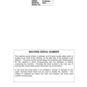
- Serial Number Information
- Ingredients
- Engine Oil
- Engine Specifications
- Hydraulic System Specifications
- Attachment Specifications
- Sprocket Dimensions and Wear Limits
- Idler Wheel Dimensions
- Upper Roller Dimensions
- Lower Roller Dimensions
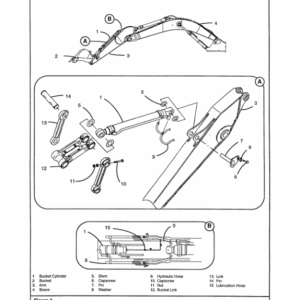
- Attachment Dimensions
- Special Torque Settings
- Machine Overall Dimensions
2. Engine
- Engine Removal and Installation
- Radiator/Oil Cooler Removal and Installation
3. Fuel System
- Fuel Tank Removal and Installation
4. Electrical System
- General Location of Components (Outside the Cab)
- Relay and Main Fuses
- General Location of Components (Inside the Cab)
- Fuse Box
- Instrument Panel
- Operating Principles
- Work Mode Selection
- H/S/L Mode Checking
- Auto Mode Checking
- Anti-Pollution System
- Acceleration Checking
- Engine Idle Checking
- Breaker Mode Checking
- Automatic Engine Preheat
- Auto Engine Warm-Up
- Idle Checking Using Battery Voltage
- Engine Emergency Stop
- Back-Up Mode
- Function Locking
- Power Boost
- Swing Brake
- Free Swing
- Travel Mode
- Travel Alarm
- Supply Cut-Off Delayed
- Hydraulic Oil Temperature Indicator
- Fuel Level
- Engine Fuel Injection Pump
- Counterweight Removal Circuit
- Access to Monitor Displays
- Machine History
- Machine Condition
- Diagnostic Code
- Warning Messages
- Excavator Model Selection Panel
- Troubleshooting
- Electrical System Troubleshooting
- Electrical Inspection of Components
- Battery Maintenance
- Maintenance of Battery
- Inspecting Battery
- Charging Battery
- Battery Charging Guide
- Connecting a Booster Battery
- Computer and Engine Controller Removal and Installation
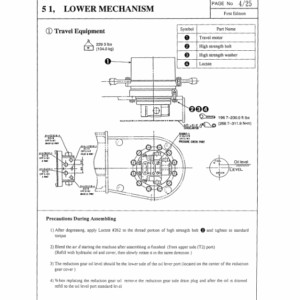
5. Undercarriage
- Track Sets Removal and Installation
- Lower Roller Removal and Installation
- Upper Roller Removal and Installation
- Checking for Leaks
- Sprocket Removal and Installation
- Idler Wheel and Tension Shock Absorber Removal and Installation
6. Drive Train
- Travel Motor/Reduction Gear Assembly Removal and Installation
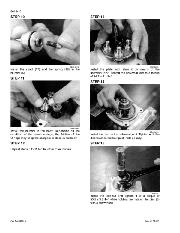
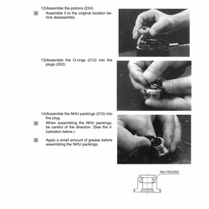
- Travel Drive Motor and Reduction Gear Disassembly and Assembly
- Swing Reduction Gear Removal and Installation
- Swing Reduction Gear Disassembly and Assembly
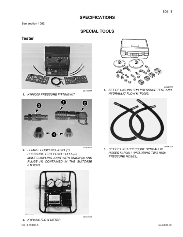
7. Hydraulics
- Releasing Pressure in Hydraulic System
- Bleeding Air from Hydraulic System
- Vacuum Pump
- Cleaning Hydraulic System
- Identification of Hydraulic Components
- Preparation Before Inspection
- Checking and Setting Procedure
- Troubleshooting
- Hydraulic Reservoir Removal and Installation
- Main Hydraulic Pump Removal and Installation
- Pilot Pump Removal and Installation
- Hydraulic Pump Coupling Removal and Installation
- Main Control Valve Removal and Installation
- Boom Cylinder Removal and Installation
- Arm Cylinder Removal and Installation
- Bucket Cylinder Removal and Installation
- Hydraulic Swivel Removal and Installation
- Pilot Function Blocks Removal and Installation
- Swing Motor Removal and Installation
- Free Swing Valve Disassembly and Assembly
- Hydraulic Pump Components
- Locating the Ports
- Regulation Control
- Removing the Controller
- Removing the Pump
- Installing the Controller
- Inspection
- Installing the Hydraulic Pump
- Control Valve Disassembly and Assembly
- Attachment Cylinders Disassembly and Assembly
- Control Lever Disassembly and Assembly
- Control Pedals Disassembly and Assembly
- Eight Solenoid Valve Bank Disassembly and Assembly
- Cushion Control Valve Disassembly and Assembly
- Boom and Safety Valves Disassembly and Assembly
- Hydraulic Swivel Disassembly and Assembly
- Hydraulic Swing Motor Disassembly and Assembly
- Hydraulic Functions
8. Upper Structure
- Upper Structure Removal and Installation
- Counterweight Removal and Installation
- Bucket Removal and Installation
- Arm Removal and Installation
- Boom Removal and Installation
- Operator’s Seat Removal and Installation
- Safety Belt Removal and Installation
- Cab Removal and Installation
- Heating Block/AC Block Removal and Installation
- Windshield Wiper Motor Removal and Installation
- Attachment Installation
- Attachment Removal and Installation
- Connecting Lower Side Frames to Upper Structure
- Procedure for Mounting Counterweight
- Operational Testing
Be the first to review “Linkbelt 800LX Excavator Service Repair Manual”
You must be logged in to post a review.
Reviews
There are no reviews yet.