Linkbelt 80 Tier 3 Spin Ace Excavator Service Repair Manual
$39.00
Manual Included:
- Service Repair Manual: 753 pages
- Operators Manual: 122 pages
- Hydraulic and Electrical Schematics
Specifications:
- Brand: LinkBelt
- Model: 80 Tier 3 Spin Ace
- Type: Excavator
- Manuals: Repair and Operators Manual
- Language: English
- Format: PDF
- Description
- Reviews (0)
Description
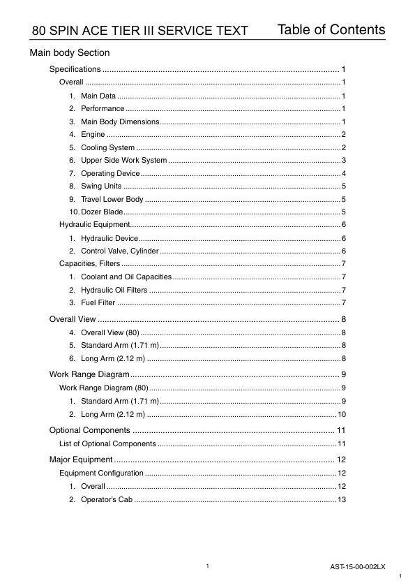
Table of Contents
Main Body Section
Specifications
- Main Data
- Performance
- Main Body Dimensions
- Engine
- Cooling System
- Upper Side Work System
- Operating Device
- Swing Units
- Travel Lower Body
- Dozer Blade
Hydraulic Equipment
- Hydraulic Device
- Control Valve, Cylinder
Capacities, Filters
- Coolant and Oil Capacities
- Hydraulic Oil Filters
- Fuel Filter
Overall View
- Overall View (80)
- Standard Arm (1.71 m)
- Long Arm (2.12 m)
Work Range Diagram
- Work Range Diagram (80)
- Standard Arm (1.71 m)
- Long Arm (2.12 m)
Optional Components
- List of Optional Components
Major Equipment
- Equipment Configuration
- Overall
- Operator’s Cab
Main Equipment Table
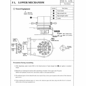
- Lower Mechanism
- Assembly Diagrams (with blade)
Lower Component
- Travel Unit
- Take-up Roller
- Upper-roller
- Lower-roller
- Recoil Spring
- Shoes
Upper Component
- Swing Unit
Engine-related
- Engine
- Muffler
- Air Cleaner (double element)
- Radiator
Hydraulic Device
- Hydraulic pump
Control-related
- Control Valve
- Solenoid Valve (4 stack)
- Remote Control Valve (left/right, travel operations)
- Remote Control Valve Characteristic Diagram
- Center Joint
Backhoe Attachment
- Cylinder
- Attachments
Fuel Tank
Sump Tank
Hydraulic Section
Hydraulic Pump Operational Description
- Configuration and Principle of Operation
Flow Control
- Constant controlling of simultaneous output
- Power-down control by discharge pressure of blade pump (blade shift)
Control Valve Operation
- Operation with All Spools in Neutral
- Main passage
- Signal passage
Independent Operation
- Travel spool switch-over (Figure 1)
- Backup spool switch-over (Figure 2)
- Swing spool switch-over (Figure 3)
- Bucket spool switch-over (Figure 3)
- Boom spool switch-over
- Arm spool switch-over
- Blade spool switch-over (Add-on) (Figure 9)
- Boom Swing spool switch-over (Add-on) (Figure 9A)
- Relief valve
- Anti-drift valve (Boom section)
Combined Operations
- Additional operation with travel (Figure 14)
Relief Valve
- Main relief valve
- Overload relief valve
Swing Unit Swing Motor
- Functional and Operational Description
- Swash Plate Motor
- Parking Brake (for models equipped with parking brakes)
- Principle of Relief Valve Operation
- Makeup Valve
- Reduction Gear (2-stage planetary gear)
Overview
- Features
- Operational Description
Travel Unit Travel Motor
- External Dimensional Drawing
- Basic Structure and Drawings
- Basic structure of GM motor
- Parts list
- Operational Description
- Reduction gear
- Hydraulic drive section
Hydraulic Circuit Section
Port Locations
- Hydraulic Pump
- Control Valve
Control Valve
Pilot Hose Connection Diagrams
- Pilot P & T Lines
- Pilot Control Lines
Functional Description
- List of Functions
- Control Valve Configuration Table
Overview
Explanation of Hydraulic Circuit and Operations (standard model)
- Travel Circuits
- High-speed Travel Circuit
- Low-speed Travel Circuit
- Straight-travel Circuit (Boom-Up and Travel-Forward)
- Swing Circuit
- Swing Parking Circuit
- Swing Override Throttle Circuit
- Bucket Circuit
- Bucket-Opening Circuit
- Arm Circuits
- Arm-in / Arm-out 2-speed Circuit
- Boom Circuits
- Boom Circuit 1: Boom-up 2-speed Circuit
- Boom Circuit 2: Boom-down Load Holding Valve Circuit
- Boom Swing Circuit
- Boom Swing Circuit
- Blade Circuits
- Blade Circuits
Explanation of Hydraulic Circuit and Operations (option)
- Backup Circuits
- Breaker and Crusher Circuit (2-speed confluence crusher circuit)
- Breaker and Crusher Circuit (breaker circuit)
- Ultra Small Tail Swing Hydraulic Excavator
- Backup Reciprocating Circuit (ultra small swing hydraulic excavator)
- Secondary Backup Reciprocating Circuit (ultra small tail swing hydraulic excavator)
Electric Circuits Section
Operational Description
- Monitor Display
- Monitor switch panel
- List of Functions
- Engine Control
- Engine start-up control
- Engine Start-up Circuit
- Monitor Output Control
- Monitor Display Control
Electric Circuit Diagrams
- Electric Circuit Diagram 1
- Electric Circuit Diagram 2
- Electric Circuit Diagram: Air Conditioner 1
- Electric Circuit Diagram: Air Conditioner 2
Harness Diagrams
- Upper Frame
- Frame Wiring Main Harness
- Inside Cab
- Cab Wiring Main Harness
Wiring Diagrams
- Electrical Components and Wiring for Upper Frame (frame)
- Electrical Components and Wiring for Cab
- Electrical Components and Wiring for Upper Frame (engine)
- Electrical Components and Wiring for Upper Frame (battery)
- Heater
- Air Conditioner
- Inside Frame
- Inside Cab
Maintenance Section
Measuring / Adjusting Pressure
- Measuring Pressure
- Basic conditions
- Pressure settings
- Ports for measuring pressure
- Preparation for Measuring Pressure
- Measuring Pressure
- Pressure adjustment
- Pressure adjusting points
- Bleeding Air
Attachments Dimensions
- Attachment Installation Methods
Appendix
- Unit Conversion Table
- New Hydraulic Oil
- Long-life hydraulic oil (IDEMITSU Daphne Super Hydro 46SX)
- Compatibility
- List of Common Features and Compatibility of Major Parts
Be the first to review “Linkbelt 80 Tier 3 Spin Ace Excavator Service Repair Manual”
You must be logged in to post a review.




Reviews
There are no reviews yet.