
Liebherr R980 SME Hydraulic Excavator Operators Service Repair Manual
Price range: $20.00 through $54.00
Manual Included:
PIN/Type – 1405, 1406
- Service Repair Manual: 2464 Pages
- Operators Manual (US & Canada version): 274 Pages
- Operators Manual (Worldwide Version): 270 Pages
PIN/Type – 1543, 1786
- Service Repair Manual: 3346 Pages
- Operators Manual (Stage IV / V Emission): 388 Pages
- Operators Manual (Stage 3A Emission): 372 Pages
PIN/Type – 1575, 1576, 1774
- Service Repair Manual: 1730 Pages
- Operators Manual: 320 Pages
Specifications:
- Type: Excavator
- Model: R980 SME
- PIN/Type: 1405, 1406, 1543, 1786, 1575, 1576, 1774
- Manuals: Operators Manual, Repair Manual
- Language: English
- Format: PDF
- Description
- Additional information
- Reviews (0)
Description
Table of Content – Liebherr R980 SME Hydraulic Excavator Type 1405, 1406 Manual
- Service manual
- Preface
- Contents
- 010 Introduction
- 010.010 Additions and updates in the service manual
- 010.020 Safety warnings
- 010.025 Standards and regulations
- 010.028 Tightening torques for pressure relief valves
- 010.032 Tightening torques for fittings
- 010.050 Special tools for maintenance and repair
- 010.051 Special tools for the hydraulic system
- 010.052 Special tools for electrical connectors
- 010.053 Special tools for Diesel engines
- 010.054 Special tools for gears
- 010.060 Conservation guidelines
- 010.080 Material weights
- 020 Technical data
- 020.005 Technical data
- 030 Maintenance
- 030.001 Sampling oils and coolant for analysis
- 030.010 Maintenance and inspection schedule
- 030.057 Confirmation of maintenance
- 030.060 Adjustment check list and procedure (from software version 103)
- 030.065 Adjustment check list and procedure (from software version 106)
- 030.070 Adjustment check list and procedure (from software version 001)
- 040 Drive group
- 040.025 SCR system
- 040.030 Coupling
- 040.045 LPV pump distributor gear
- 050 Cooling system
- 050.010 Cooling system
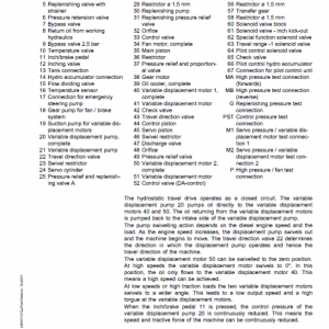
- 060 Working hydraulics
- 060.001 List of hydraulic diagrams
- 060.005 Overview of hydraulic symbols
- 060.020 Depressurising a hydraulic system
- 060.028 Description of the hydraulic system
- 060.030 Components list
- 060.032 Hydraulic schematic – backhoe bucket attachment
- 060.035 Hydraulic schematic – bottom dump shovel attachment
- 060.058 Description of the hydraulic system
- 060.060 Components list
- 060.063 Hydraulic schematic – backhoe bucket attachment
- 060.064 Hydraulic schematic – backhoe attachment
- 060.070 Hydraulic schematic – bottom dump shovel attachment
- 060.071 Hydraulic schematic – shovel attachment
- 060.075 Hydraulic schematic – backhoe bucket attachment
- 060.076 Hydraulic schematic – backhoe attachment
- 060.080 Hydraulic schematic – bottom dump shovel attachment
- 080 Hydraulic components
- 080.010 List of the hydraulic pumps
- 080.015 Rotary group for axial piston pumps and motors
- 080.040 LPV variable-displacement pump
- 080.055 LR-SD-DA regulator
- 080.100 Variable-displacement pump A4 VG
- 080.170 Pump for distribution gear oil cooling
- 080.175 Gear pumps AZP
- 080.200 Control oil unit
- 080.220 Pilot control unit / joystick
- 080.230 Pilot control unit / travel pedal
- 080.240 Pilot control unit / lateral double pedal
- 080.303 Axial piston hydraulic motor MT45
- 080.305 FMF hydraulic motor – line A
- 080.315 FMV travel motor
- 080.320 Travel brake valve (motor type FMV)
- 080.400 1-way rotary connection
- 080.405 5-way rotary connection
- 080.500 Pressure relief valves
- 110 Electrical system
- 110.001 List of electrical diagrams
- 110.005 Overview of electrical symbols
- 110.010 Operator’s cab – arrangement of electrical components
- 110.030 Operator’s cab – electrical diagrams
- 110.070 Operator’s cab – arrangement of electrical components
- 110.071 Operator’s cab – electrical diagrams
- 110.200 Uppercarriage – arrangement of electrical components
- 110.210 Uppercarriage – electrical diagrams
- 110.400 Uppercarriage – arrangement of electrical components
- 110.420 Uppercarriage – electrical diagrams
- 53-1
- 110.550 Uppercarriage – main cable set
- 110.700 Liebherr Diesel engine – arrangement of electrical components
- 110.740 Diesel engine D936 – electrical diagrams
- 110.760 Liebherr Diesel engine – arrangement of electrical components
- 110.780 Diesel engine D9508 – electrical diagrams
- SCHALTPLAN ELEKTRIK
- INHALTSVERZEICHNIS
- EINBAULAGE ELEKTRISCHE BAUTEILE
- EINBAULAGE ELEKTRISCHE BAUTEILE
- MOTOR ÜBERSICHT
- MOTORSTEUERGERÄT
- MOTORSTEUERGERÄT
- MOTORSTEUERGERÄT
- MOTORSTEUERGERÄT
- LICHTMASCHINE, ANLASSER
- ÖLDRUCKGEBER, KRAFTSTOFFDRUCKGEBER,
- RAILDRUCKGEBER 1-2
- LADELUFTTEMPERATURGEBER, KÜHLWASSERTEMPERATURGEBER
- MENGENREGELVENTIL, TAKTVENTIL
- DREHZAHLGEBER 1, PHASENGEBER
- EINSPRITZDÜSEN ZYL. 1-4
- EINSPRITZDÜSEN ZYL. 5-8
- HEIZFLANSCH MIT MASSE 1-2
- ZEICHENERKLÄRUNG
- BMK-VERZEICHNIS
- 120 Travel gearbox
- 120.005 List of travel gear mechanisms
- 120.015 Travel gear mechanism – line P(r)
- 120.020 Travel brakes
- 120.210 Adjusting the secondary pressure-relief valves for travel gear movements (motor type FMV)
- 130 Travel gear
- 130.100 Arrangement of track components
- 130.400 Wear on the track components
- 130.410 Wear limits for the track components
- 130.450 Identification of the crawler chain type
- 130.500 Track complete
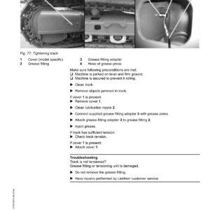
- 130.530 Repair of a track
- 130.600 Tension unit complete
- 130.630 Idler-wheel
- 130.650 Grease tensioner
- 130.750 Preassembled spring tensioner
- 130.770 Two-loose-spring tensioner
- 130.800 Track roller
- 130.860 Carrier roller supported on both sides
- 130.900 Face seals
- 140 Steel parts of the basic machine
- 140.010 Repair welding guideline
- 150 Working attachment
- 150.010 Hydraulic cylinders
- 150.090 Stick and hoist cylinder shut-down
- 150.095 Stick cylinder protection (damping)
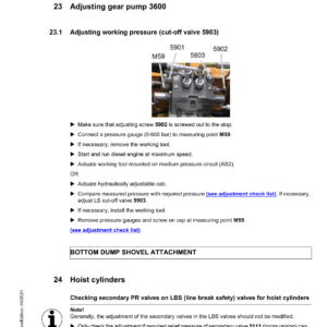
- 150.100 Regeneration and dine break safety valve for hoist cylinder
- 150.115 Regeneration and line break safety valve for stick cylinder
- 150.350 Preparation for third party hydraulic quick coupler
- 150.400 Removing and installing the stick to the boom
- 160 Cab, heating and air conditioning
- 160.055 Air conditioning unit: design and function
- 160.060 Air conditioning unit: malfunctions
- 160.065 Air conditioning unit: maintenance
- 160.070 Air conditioning unit: repair
- 160.100 Hydraulically adjustable cab
- 160.105 Auxiliary heater
- 170 Lubrication system
- 170.010 Central lubrication system
- 170.020 Troubleshooting
- 170.030 Lubrication pump
- 170.040 Progressive distributor SXE-2
- 170.050 Progressive distributor MX-F
- 170.060 Installing and repairing lubrication hoses
- 180 Slewing gearbox and slewing ring
- 180.010 Slewing gear mechanism SAT
- 180.050 Slewing ring
- 190 Equipment and options
- 190.010 High pressure circuit 1
- 190.030 High pressure circuit 2
- 190.050 Bottom dump shovel control
- 190.065 Medium pressure circuit (AS2)
- 190.080 Hydraulically adjustable cab
- 190.100 Stick and hoist cylinder shut-down
- 190.112 Hoist cylinder protection
- 190.115 Stick cylinder protection (damping)
- 190.120 Hydraulic quick change system
- 190.122 Preparation for third party hydraulic quick coupler
- 190.127 Tool Management
- 190.130 Line break safety valve for attachment cylinders
- 190.155 Watering device
- 190.160 Bypass filter
- 190.165 Hydraulic hammer return filter
- 190.170 Changing over the control
- 190.172 Bypass to open the shear
- 190.175 Slewing gear brake (pedal)
- 190.180 Special working attachments and tools
- 190.190 LiDAT remote diagnosis system (LiTU 2 – Master 4)
- 190.195 Radio
- 190.200 Headlights and beacon
- 190.310 Electric refuelling pump
- 190.320 Pre-heating
- 190.325 Activating the reverse air jet for cleaning the cooler
- 190.327 Tropical execution
- 190.330 Auxiliary heater
- 190.400 Travel alarm
- 190.410 Screen wiper
- 190.415 Overload warning system
- 190.430 Immobiliser
- 190.440 Video surveillance
- 190.460 Pressure cut-off (DA)
- 200 Diagnosis
- 200.005 Updating the machine software (Master 4)
- 200.050 Recording error messages of master module
- 200.070 Incompatibility of functions
- 200.072 Incompatibilities of the options
- 200.200 CAN data transmission
- 200.260 CAN input and output modules
- 200.270 Addressing of CAN modules
- 200.405 Troubleshooting for camera
- 200.410 Display
- 200.505 Connection to Sculi
- 200.530 Sculi – access to the variables
- 200.600 Sculi – Wizard utility
Additional information
| PIN Type | Type 1405 & 1406, Type 1543 & 1786, Type 1575 & 1576 & 1774 |
|---|---|
| Manual | Service Repair Manual, Operators Manual (US & Canada version), Operators Manual (Worldwide Version), Operators Manual (Stage IV / V Emission), Operators Manual (Stage 3A Emission), Operators Manual |
Be the first to review “Liebherr R980 SME Hydraulic Excavator Operators Service Repair Manual”
You must be logged in to post a review.
Reviews
There are no reviews yet.