

Liebherr R924 Hydraulic Excavator Operators Service Repair Manual
Price range: $15.00 through $54.00
Manual Included:
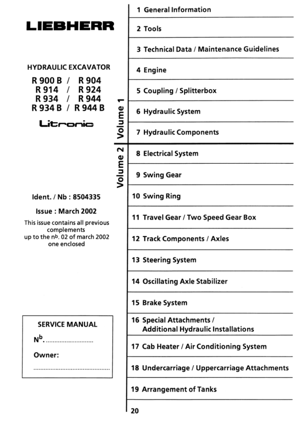
PIN/Type – 645, 646, 676, 677, 734, 740
- Service Repair Manual: 1233 Pages
- Operators Manual (SN after 6400): 188 Pages
- Operators Manual (SN 6100: 6400) – 174 Pages
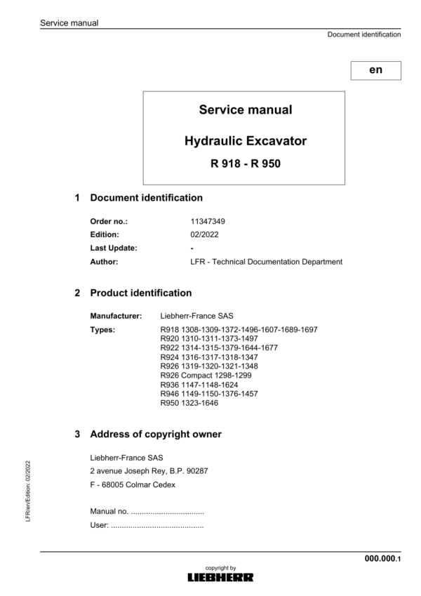
PIN/Type – 1316, 1317, 1318,1347
- Service Repair Manual: 3360 Pages
- Operators Manual (Standard Version): 356 Pages
- Operators Manual (US & Canada version): 350 Pages
- Operators Manual (Teleskop Version, SN after 47887): 308 Pages
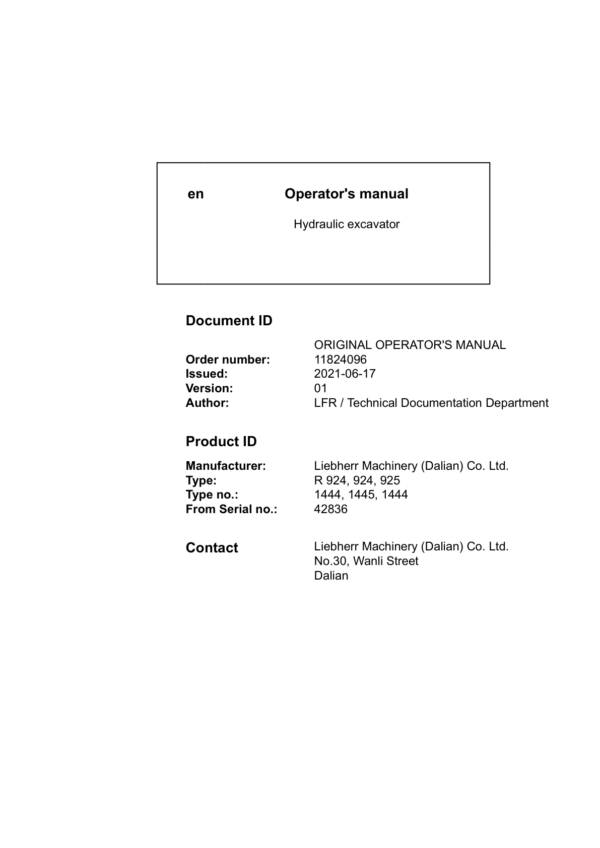
PIN/Type – 1444 & 1445
- Service Repair Manual: 916 Pages
- Operators Manual (SN 40692: 42835) – 232 Pages
- Operators Manual (SN after 42836): 324 Pages
PIN/Type – 1487
- Service Repair Manual: 1770 Pages
- Operators Manual (Stage V Emission: worldwide version) – 428 Pages
- Operators Manual (US & Canada version): 424 Pages
- Operators Manual (Stage 4f Emission: worldwide version) – 420 Pages
Specifications:
- Type: Excavator
- Model: R924
- PIN/Type: 645, 646, 676, 677, 734, 740, 1316, 1317, 1318,1347, 1444 & 1445, 1487
- Manuals: Operators Manual, Repair Manual
- Language: English
- Format: PDF
- Description
- Additional information
- Reviews (0)
Description
Table of Content – Liebherr R924 Hydraulic Excavator Type 1487 Manual
- Service manual
- Preface
- Contents
- 010 Introduction
- 010.010 Additions and updates in the service manual
- 010.020 Safety warnings
- 010.025 Standards and regulations
- 010.050 Special tool
- 010.060 Conservation guidelines
- 010.080 Material weights
- 020 Technical data
- 020.005 Technical data
- 030 Maintenance
- 030.005 Maintenance
- 030.010 Confirmation of maintenance
- 030.060 Adjustment checklist R922 and R924
- 030.100 Preparations
- 030.105 Machine-specific data
- 030.110 Operating conditions
- 030.130 External setting sensors
- 030.140 Diesel engine
- 030.150 Servo control
- 030.160 Control elements
- 030.170 Board instruments
- 030.200 CPVP Working pump
- 030.210 DPVP Working pump
- 030.220 LH Working pump
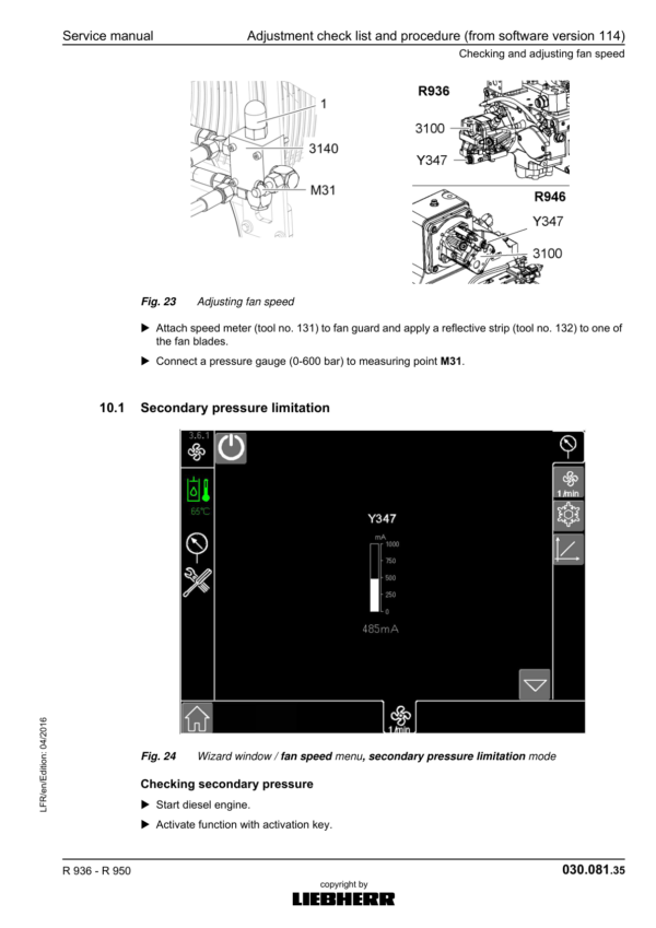
- 030.240 Fan
- 030.250 Engine power (Powertest)
- 030.310 Proportional solenoid valves block 4850
- 030.330 E-valves
- 030.350 Secondary pressure relief valves
- 030.355 Secondary pressure relief valves, with telescopic attachment
- 030.370 High pressure circuit 1 (option)
- 030.380 Float position of the boom (option)
- 030.385 High pressure circuit 2 (option)
- 030.390 Primary pressure relief valve
- 030.395 Height-adjustable special boom (option)
- 030.500 Slewing motor
- 030.510 A4VG Slewing pump
- 030.520 DPVG slewing pump
- 030.600 Travel motors
- 030.710 Standby pressure
- 030.720 Secondary pressure relief valves
- 030.750 Working pressure
- 030.770 Start of movement
- 040 Drive group
- 040.020 Diesel engine D934 A7/ D944 A7
- 040.021 Diesel engine D924 A7-05
- 040.025 SCR exhaust treatment system
- 040.026 SCR exhaust gas treatment system
- 040.027 SCRF exhaust treatment system
- 040.028 SCRF exhaust gas treatment system
- 040.029 Exhaust system without exhaust gas treatment
- 040.030 Diesel exhaust fluid system
- 040.035 Fuel system
- 040.040 Air filter system
- 040.061 Coupling
- 050 Cooling system
- 050.010 Cooling unit
- 050.020 Fan drive
- 050.030 Reversible fan drive
- 060 Working hydraulics
- 060.001 List of hydraulic diagrams
- 060.005 Overview of hydraulic symbols
- 060.007 Colour code for lines in hydraulic schematics
- 060.010 Description of positive control system
- 060.050 Design of hydraulic system
- 060.060 Components list
- 060.070 Hydraulic schematic
- 060.100 Design of hydraulic system Valid for machines with DPVP working pump
- 060.110 Components list
- 060.120 Hydraulic schematic
- 060.200 Description of hydraulic circuit Valid for machines with LH working pump
- 060.210 Components list
- 060.220 Hydraulic schematic
- 060.910 Component list
- 060.920 Hydraulic schematic
- 070 Travel hydraulics
- 080 Hydraulic components
- 080.015 Hydraulic tank
- 080.019 Rotary group of axial piston pumps and motors
- 080.020 SL-SD regulator
- 080.024 CPVP double variable-displacement pump
- 080.025 DPVP double variable-displacement pump
- 080.027 A4VG slewing pump
- 080.029 Servo control pump
- 080.040 Fan pump
- 080.045 Gear pump of small flow circuit
- 080.047 Variable-displacement pump of the small flow circuit
- 080.050 Control valve block
- 080.055 Proportional solenoid valve block
- 080.076 Rotary connection 6x
- 080.080 Hydraulic differential cylinder
- 080.090 Accumulator
- 080.100 Line break safety valves of hoist cylinder
- 080.105 Line break safety valve of stick cylinder
- 080.110 Load-holding valve of bucket cylinder
- 080.200 Servo control unit
- 110 Electrical system
- 110.001 List of electrical diagrams
- 110.005 Overview of electrical symbols
- 110.006 Circuit diagrams in LIDOS
- 110.008 Overview of ground points
- 110.101 Operator’s cab – electrical diagrams
- 110.201 Uppercarriage – electrical diagrams
- 110.250 Uppercarriage – main cable set
- 110.310 Diesel engine environment – electrical diagrams
- 110.410 Diesel engine D924 – electrical diagrams
- 110.460 Diesel engine D9x4 A7 – electrical diagrams
- 120 Travel gearbox
- 120.050 Travel gearbox FAT
- 130 Travel gear
- 130.100 Arrangement of track components
- 130.210 List of the track components
- 130.410 Wear limits for the track components
- 130.500 Track complete
- 130.530 Repair of a track
- 130.600 Tension unit complete
- 130.630 Idler-wheel
- 130.650 Grease tensioner
- 130.700 Monoblock tensioner
- 130.750 Preassembled spring tensioner
- 130.800 Track roller
- 130.850 Carrier roller supported on one side
- 130.900 Face seals
- 140 Steel parts of the basic machine
- 140.010 Repair welding guideline
- 140.100 Counterweight
- 150 Working attachment
- 150.010 Hydraulic cylinders
- 150.180 Load-holding valve for bucket cylinder
- 150.210 Bucket cylinder or grapple cylinder supply circuit
- 150.450 Stick extension on high pressure circuit
- 150.500 Telescopic attachment
- 150.800 Support blade
- 160 Cab, heating and air conditioning
- 160.021 Auxiliary heater
- 160.035 Heating and air conditioning unit
- 160.041 Air conditioning
- 170 Lubrication system
- 170.001 Repair of lubrication hose
- 170.005 Automatic central lubrication system
- 170.015 Central lubrication pump
- 170.025 Progressive distributor
- 180 Slewing gearbox and slewing ring
- 180.010 Slewing gearbox SAT
- 180.500 Slewing ring
- 180.600 Slewing ring: changing the grease
- 180.700 Slewing ring: draining water
- 190 Equipment and options
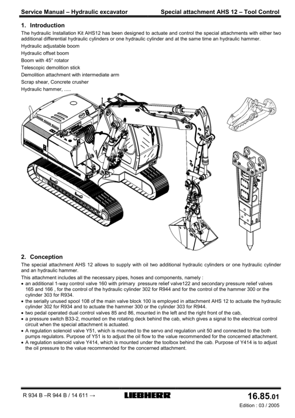
- 190.005 Tool control
- 190.010 High pressure circuit 1
- 190.030 High pressure circuit 2
- 190.040 Small flow circuit
- 190.050 Tool Management
- 190.060 Medium pressure circuit
- 190.075 Tiltrotator
- 190.077 Dual circuit tiltrotator
- 190.080 Hydraulically adjustable cab
- 190.100 Movement restriction for stick and movement restriction for boom
- 190.118 Float position of the boom
- 190.122 Preparation for hydraulic quick couplers from manufacturers
- 190.125 LIKUFIX hydraulic coupling system
- 190.135 Mowing bucket
- 190.140 Hydraulically adjustable undercarriage width
- 190.150 Generator
- 190.155 Watering device
- 190.160 Bypass filter
- 190.165 Return filter for hydraulic hammer
- 190.183 Clamp on undercarriage
- 190.185 Laterally adjustable boom
- 190.190 LiDAT remote diagnosis system (LiTU 3 – Master 5)
- 190.192 Remote diagnostic system (China)
- 190.195 Radio
- 190.210 Locking / enabling the machine
- 190.305 Electric fuel refuelling pump
- 190.323 Air flow reversal for radiator cleaning
- 190.400 Travel alarm system
- 190.430 Immobiliser
- 190.440 Video surveillance
- 200 Diagnosis
- 200.008 Update of the machine software (Master 5)
- 200.010 Connect SCULi diagnostic software (Master 5)
- 200.015 LiFT function (Master 5)
- 200.020 Service file (Master 5)
- 200.025 Reset Master (Master 5)
- 200.030 Machine software backup (Master 5)
- 200.100 Liebherr diagnosis tool LIDIA
- 200.150 SCR system check
- 200.260 CAN modules
- 200.300 Malfunctions
- 200.400 Addressing of side area camera
- 200.405 Troubleshooting for camera
- 200.420 Standalone display
- 200.600 SCULi – Wizard assistant
- 200.605 SCULi – working attachment adjustment
- 200.620 Replacing components
Additional information
| PIN Type | Type 645 & 646 & 676 & 677 & 734 & 740, Type 1316 & 1317 & 1318 &1347, Type 1444 & 1445, Type 1487 |
|---|---|
| Manual | Service Repair Manual, Operators Manual (SN after 6400), Operators Manual (SN 6100 – 6400), Operators Manual (Standard Version), Operators Manual (US & Canada version), Operators Manual (Teleskop Version, SN after 47887), Operators Manual (SN 40692 – 42835), Operators Manual (SN after 42836), Operators Manual (Stage V Emission – Worldwide Version), Operators Manual (Stage 4f Emission – Worldwide Version) |
Be the first to review “Liebherr R924 Hydraulic Excavator Operators Service Repair Manual”
You must be logged in to post a review.
Reviews
There are no reviews yet.