

Liebherr D9508 A7-05 Diesel Engine Service Repair Manual
$42.00
Manual Included:
- Service Repair Manual: 596 Pages
- Operators Manual: 206 Pages
Specifications:
- Brand: Liebherr
- Model: D9508 A7-05
- Type: Diesel Engine
- Manuals: Operators & Service Repair Manual
- Language: English
- Format: PDF
- Description
- Reviews (0)
Description
Table of Content (D9508 A7-05 Repair Technical Manual)
1 Product description
1.1 Technical description
1.1.1 Engine components
1.1.2 Exhaust aftertreatment system SCRFilter (double-flow)
1.1.3 Reduction agent pump
1.1.4 Control unit SCR NH3 sensor
1.1.5 Engine type itemization
1.1.6 Firing order
1.1.7 Cylinder designation
1.1.8 Direction of rotation
1.1.9 Company nameplate
1.1.10 Engine control unit type plate
1.1.11 Exhaust aftertreatment system type plate
1.1.12 DOC, mixing pipe and sensor pipe
1.1.13 Exhaust aftertreatment system SCRFilter (double-flow)
1.1.14 Exhaust gas turbocharger type plate
1.1.15 Injector code
1.1.16 Company name plate for fuel high pressure pump
1.2 Technical data
1.2.1 Cylinder liner projection
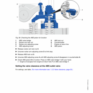
1.2.2 Valve clearance
1.2.3 Piston ring end gap
1.2.4 Thermostat start of opening
1.3 Functional description
1.3.1 Fuel system
1.3.2 Lubrication system
1.3.3 Cooling system
1.3.4 Charge air system
1.3.5 Assignment of the channels in the crankcase and in the cylinder head
1.3.6 Exhaust aftertreatment system SCRFilter (double-flow)
1.3.7 Reduction agent pump
2 Safety
2.1 Labeling of warnings
2.1.1 Additional labels
2.2 Target group
2.2.1 International Standard Classification of Occupations
2.2.2 Occupational references
2.2.3 Unauthorized personnel
2.3 Intended use
2.4 Foreseeable misuse
2.5 General safety instructions
2.6 Preventing personal injuries
2.6.1 Bruises
2.6.2 Burns and scalds
2.6.3 Fires and explosions
2.6.4 Poisoning
2.6.5 High-pressure injection (liquids at high pressure can squirt out)
2.6.6 Electrical energy
2.6.7 Danger due to noise
2.7 Personal protective equipment
2.8 Operating areas and maintenance areas
2.8.1 Safety instructions
2.8.2 Operating areas
2.8.3 Maintenance areas
2.8.4 Securing and releasing the diesel engine against accidental start-up
2.8.5 Emergency stop
2.9 Signage
2.10 Preventing property damage
3 Repair work
3.1 Removing and installing the cover plate
3.1.1 Removing the cover plate
3.1.2 Installing the cover plate
3.2 Cylinder head cover
3.2.1 Removing and installing the cylinder head cover
3.2.2 Installing the cylinder head cover seal
3.2.3 Removing and installing the crankcase ventilation of the cylinder head cover
3.2.4 Removing and installing the oil filler neck of the cylinder head cover
3.2.5 Installing the oil filler neck of the cylinder head cover
3.3 Cylinder head
3.3.1 Checking and setting the valve clearance
3.3.2 Rocker arm bracket and push rods
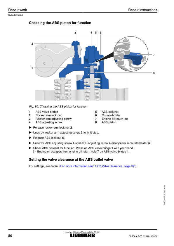
3.3.3 Removing and installing the valve bridges with auxiliary brake system
3.3.4 Removing and installing the cylinder head
3.3.5 Valves and valve stem seal
3.3.6 Removing and installing the roller plunger
3.3.7 Removing and installing the camshaft
3.4 Driving gear
3.4.1 Piston with connecting rod
3.4.2 Piston rings
3.4.3 Removing and installing the cylinder liner
3.4.4 Checking the projection of the cylinder liners
3.4.5 Belt pulley
3.4.6 Torsional vibration damper
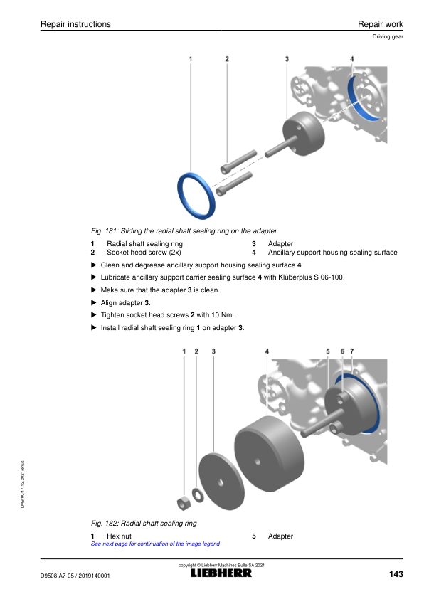
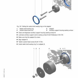
3.4.7 Ancillary support housing side radial shaft sealing ring
3.4.8 Removing and installing the ancillary support housing
3.4.9 Removing and installing the intermediate wheel
3.4.10 Flywheel
3.4.11 Flywheel side radial shaft sealing ring
3.4.12 Removing and installing the crankshaft gear wheel
3.4.13 Removing and installing the flywheel housing
3.4.14 Crankshaft
3.4.15 Removing and installing the locking pieces of the crankcase
3.5 Fuel system
3.5.1 Safety instructions for working on the fuel system
3.5.2 Removing and installing the fuel lines
3.5.3 Removing and installing the fuel return lines
3.5.4 Reducing the pressure in the fuel system
3.5.5 Fuel injection pipes
3.5.6 Removing and installing the injection pipes
3.5.7 Removing and installing the fuel rails
3.5.8 Removing and installing the pressure pipe socket and injector
3.5.9 Removing and installing the fuel filter module
3.5.10 Fuel high pressure pump
3.5.11 High pressure pump drive
3.6 Belt drive
3.6.1 Removing and installing the V-ribbed belt
3.6.2 Removing and installing the tension pulley (self-tensioning)
3.6.3 Removing and installing the fan
3.7 Charge air system
3.7.1 Removing and installing the charge air pipe
3.7.2 Removing and installing the connection line
3.7.3 Air intake manifold
3.7.4 Removing and installing the left intake manifold
3.7.5 Removing and installing the right intake manifold
3.7.6 Removing and installing the charge air pipe
3.7.7 Pressure regulation
3.8 Exhaust system
3.8.1 Exhaust gas stub
3.8.2 Exhaust gas turbocharger
3.8.3 Exhaust manifold
3.9 Engine oil system
3.9.1 Commissioning the engine after a repair to the engine oil system
3.9.2 Removing and installing the end control valve
3.9.3 Crankcase ventilation
3.9.4 Oil module
3.9.5 Oil cooler
3.9.6 Oil pan
3.9.7 Oil pumps
3.9.8 Removing and installing the piston cooling nozzle
3.10 Cooling system
3.10.1 Removing and installing the ventilation lines
3.10.2 Removing and installing the coolant connections
3.10.3 Coolant pump
3.10.4 Thermostat
3.10.5 Removing and installing the water manifold
3.11 Auxiliary output
3.11.1 Air conditioning compressor (optional)
3.11.2 Air compressor (optional)
3.11.3 Removing and installing power take off 1
3.11.4 Removing and installing power take off 2
3.12 Electrical system
3.12.1 Heating flange
3.12.2 Alternator
3.12.3 Removing and installing the starter motor
3.12.4 Engine control unit
3.12.5 Sensors
3.12.6 Cable harness
3.13 Exhaust aftertreatment system
3.13.1 Safety instructions for working on the exhaust aftertreatment system (SCR system)
3.13.2 Removing the mixing pipe
3.13.3 Install mixing pipe
3.13.4 Remove reduction agent injector
3.13.5 Install reduction agent injector
3.13.6 Removing the sensor pipe
3.13.7 Install sensor pipe
3.13.8 Exhaust regulation sensors
3.13.9 Remove reduction agent pump
3.13.10 Install reduction agent pump
3.13.11 Removing and installing the reduction agent suction module
3.13.12 Exhaust aftertreatment system tightening torques
3.14 SCRF exhaust aftertreatment system
3.14.1 Removing the diesel oxidation catalyst
3.14.2 Install diesel oxidation catalyst
3.14.3 Removing the inlet module
3.14.4 Installing the inlet module
3.14.5 Removing the SCRF outlet module
3.14.6 Installing the SCRF outlet module
3.14.7 Removing the pressure measurement lines
3.14.8 Removing the filter module (double-flow)
3.14.9 Installing the filter module (double-flow)
3.14.10 Installing the pressure measurement line
4 Tools and devices
4.1 Tools
4.1.1 Special tools
4.1.2 Protecting caps for fuel system
4.1.3 Diagnostic tools
4.2 Devices
4.2.1 Lifting traverse with three-point-raising
4.2.2 Engine assembly stand
4.2.3 Adapter for fastening the engine to the engine assembly stand
4.2.4 Removing and installing the lifting hook
5 Assembly agents
6 Appendix
6.1 Tightening torques
6.1.1 Hex head screws / hexagon socket screws / hexalobular flange head screws
6.1.2 Screw plugs and banjo bolts with separate seal
6.1.3 VSTI screw plugs
6.1.4 Threaded union for steel or cast iron mating materials
6.1.5 Threaded union for aluminum mating material
6.1.6 Nut for cutting ring screw fittings
6.1.7 Nut for Triple Lok® screw fittings
6.1.8 Adapter for plastic quick couplings
6.1.9 Stud bolts
Be the first to review “Liebherr D9508 A7-05 Diesel Engine Service Repair Manual”
You must be logged in to post a review.
Reviews
There are no reviews yet.