
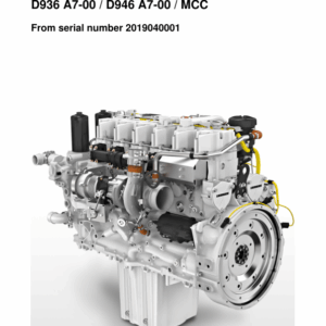
Liebherr D936 A7-00, D946 A7-00 MCC (Mechanical Common Rail) Diesel Engine Operators Manual
$28.00
Manual Included:
- Operators Manual: 144 Pages
Specifications:
- Brand: Liebherr
- Model: D936 A7-00, D946 A7-00 MCC
- Type: Diesel Engine
- Manuals: Operators Manual
- Language: English
- Format: PDF
- Description
- Reviews (0)
Description
Table of Content (D936 A7-00, D946 A7-00 MCC – Operators Manual)
1 Product description
1.1 Technical description
1.1.1 Engine components
1.1.2 Company nameplate
1.1.3 Firing order, cylinder designation and engine serial number
1.1.4 Direction of rotation
1.1.5 Engine control unit type plate (ECU2)
1.2 Technical data
1.2.1 Diesel engine
1.2.2 Valve clearance
1.2.3 Valve clearance, auxiliary braking system (ABS)
1.2.4 Coolant thermostat
2 Safety
2.1 Labeling of warnings
2.1.1 Additional labels
2.2 Target group
2.3 Intended use
2.4 Foreseeable misuse
2.5 General safety instructions
2.6 Preventing personal injuries
2.6.1 Bruises
2.6.2 Burns and scalds
2.6.3 Fires and explosions
2.6.4 Poisoning
2.6.5 High-pressure injection (liquids at high pressure can squirt out)
2.6.6 Electrical energy
2.6.7 Danger due to noise
2.7 Personal protective equipment
2.8 Operating areas and maintenance areas
2.8.1 Safety instructions
2.8.2 Operating areas
2.8.3 Maintenance areas
2.8.4 Securing and releasing the diesel engine against accidental start-up
2.8.5 Emergency stop
2.9 Signage
2.10 Preventing property damage
3 Transport and storage
3.1 Dimensions and weights
3.2 Lifting the engine
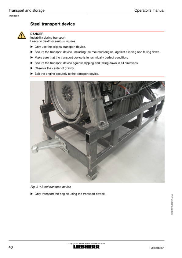
3.3 Transport
3.3.1 Transport attachment
3.3.2 Transport device
3.4 Storage
3.4.1 Storage
3.4.2 Storage time
4 Operation
4.1 Preliminary work for the initial commissioning of the engine
4.2 Starting the engine
4.3 Turning off the engine
5 Maintenance
5.1 Maintenance schedule
5.2 Preliminary work
5.2.1 Bringing the engine into maintenance position
5.2.2 As needed
5.3 Diesel engine
5.3.1 Checking the V-ribbed belt for damage
5.3.2 Checking the V-ribbed belt for tension
5.3.3 Checking the belt drive
5.3.4 Replacing the belt drive
5.3.5 Checking the engine mount
5.3.6 Checking the intake system for leaks and damage
5.3.7 Checking the exhaust system
5.4 Engine oil system
5.4.1 Checking the engine oil system for leaks and damage
5.4.2 Checking the engine oil level
5.4.3 Changing the engine oil
5.4.4 Replacing the oil separator filter insert
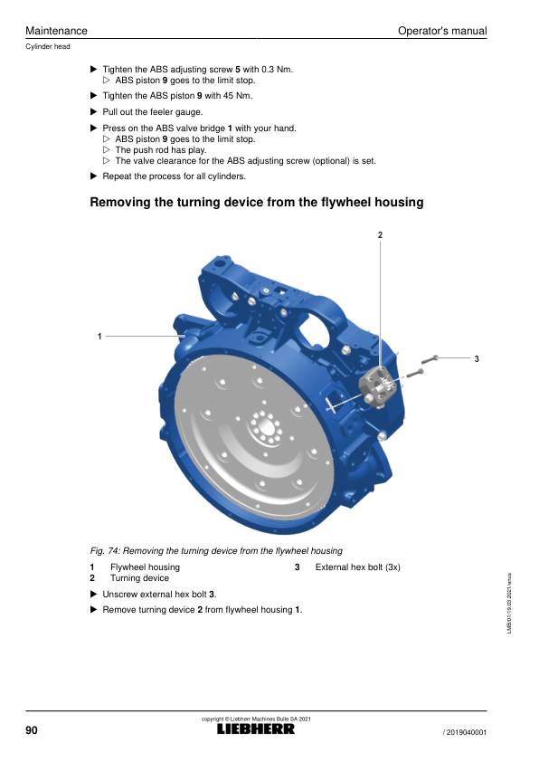
5.5 Cylinder head
5.5.1 Checking and setting the valve clearance
5.6 Cooling system
5.6.1 Checking the cooling system and heating system for leaks and damage
5.6.2 Checking the coolant level
5.6.3 Checking the concentration of the antifreeze agent in the coolant
5.6.4 Replacing the coolant
5.7 Fuel system
5.7.1 Checking the fuel system for leaks and damage
5.7.2 Replacing the fuel prefilter
5.7.3 Reducing the pressure in the fuel system
5.7.4 Replacing the fuel fine filter
5.7.5 Ventilating the fuel system
5.8 Air filter
5.8.1 Checking the air filter low pressure indicator
5.8.2 Cleaning the air filter dust discharge valve
5.8.3 Replacing the dry air filter main element
5.8.4 Replacing the dry air filter safety element
5.9 Electrical system
5.9.1 Checking the batteries
5.9.2 Checking the cable connections
5.9.3 Checking the engine control unit bearings for damage
5.9.4 Checking sensors, actuators, cable holders and plugs
5.9.5 Checking the heating flange
5.9.6 Replacing the heating flange
5.10 Lubricants and operating fluids
5.10.1 Fill quantities
5.10.2 Engine oil for diesel engines without emission type approval
5.10.3 Coolant
5.10.4 Fuel for diesel engines without emission type approval
6 Malfunctions
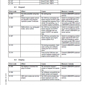
6.1 Faults – Cause – Remedy
7 Tools and devices
7.1 Tools
7.1.1 Special tool
7.1.2 Assembly agents
7.1.3 Diagnostic tools
7.2 Devices
7.2.1 Lifting traverse with two-point-raising (basic version)
7.2.2 Lifting traverse with two-point-raising
7.2.3 Engine assembly stand
7.2.4 Transport device
8 Appendix
8.1 Tightening torques
8.1.1 For hex bolts / cylinder screws / external hex bolts
8.1.2 For locking screws and banjo bolts
8.1.3 Standard torques for metric flange connections
8.1.4 Metric screw connection series L (light) (up to 500 bar/7252 Psi)
8.1.5 Metric screw connection series S (heavy) (up to 800 bar/11603 Psi)
8.1.6 Inch screw connection series L (light) (up to 500 bar/7252 Psi)
8.1.7 Inch screw connection series S (heavy) (up to 800 bar/11603 Psi)
8.1.8 Metric thread unit series L (light) (up to 500 bar/7252 Psi) for aluminum
Be the first to review “Liebherr D936 A7-00, D946 A7-00 MCC (Mechanical Common Rail) Diesel Engine Operators Manual”
You must be logged in to post a review.
Reviews
There are no reviews yet.