
Liebherr D934 A7 SCR, D936 A7 SCR, D946 A7 SCR Diesel Engine Service Repair Manual
$30.00
Manual Included:
- Service Repair Manual: 102 Pages
- Operators Manual: 112 Pages
Specifications:
- Brand: Liebherr
- Model: D934 A7 SCR, D936 A7 SCR, D946 A7 SCR
- Type: Engine
- Manuals: Service Repair Manual & Operators Manual
- Language: English
- Format: PDF
- Description
- Reviews (0)
Description
Table of Content of the D934 A7 SCR, D936 A7 SCR, D946 A7 SCR Service Manual:
1 General information
1.1 Structure of this manual
1.2 Important notes within this manual
1.2.1 Designation of activity-related notes on safety
1.2.2 Further designations
1.3 Symbols in this manual
1.4 Notes on safety
1.4.1 General notes on safety
1.4.2 Preventing injury to persons
1.4.3 Preventing damage to property
1.5 Notes regarding working on the fuel system and injection system
1.5.1 General notes on safety
1.5.2 Preventing injury to persons
1.5.3 Preventing damage to property
1.6 Notes on safety for working on the exhaust after-treatment system (SCR system)
1.6.1 Carbamide solution
1.6.2 General notes on safety
1.6.3 Preventing injury to persons
1.6.4 Preventing damage to property
1.7 Technical Data
1.7.1 Engine in general
1.7.2 Standard tightening torques for screw connections
1.7.3 Standard torques for locking screws and banjo bolts
1.7.4 Standard torques for metric threaded unions
1.7.5 Standard torques for imperial threaded unions
1.7.6 Standard torques for cutting ring threaded unions
1.7.7 Standard torques for Triple Lock threaded unions
1.7.8 Standard torques for VSTI screw plugs
1.7.9 Special torques, tightening specifications, installation specifications and installation instructions
General notes
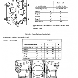
Tightening specification for main bearing
Tightening specification for aggregate carrier
Tightening specification for piston cooling nozzle
Tightening specification for final regulating valve and cold start valve
Tightening specification for oil intake
Tightening specification for oil drain valve
Tightening specification for oil sump (D934)
Tightening specification for oil sump (D936 / D946)
Tightening specification for crankshaft accessories
Tightening specification for connecting rod
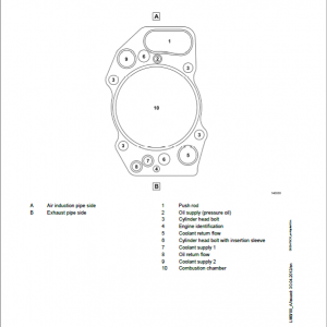
Tightening specification for cylinder head
Installation and tightening specification for counterbalancing shafts (D934)
Tightening specification for rocker arm support
Installation and tightening specification for camshaft
Tightening specification for oil cooler
Tightening specification for oil cooler housing (D934)
Tightening specification for oil cooler housing (D936 / D946)
Tightening specification for fitting in oil filter bracket
Installation and tightening specification for high-pressure pump
Installation and tightening specification for injector and pressure pipe tube
Installation instruction for cable harness on injector
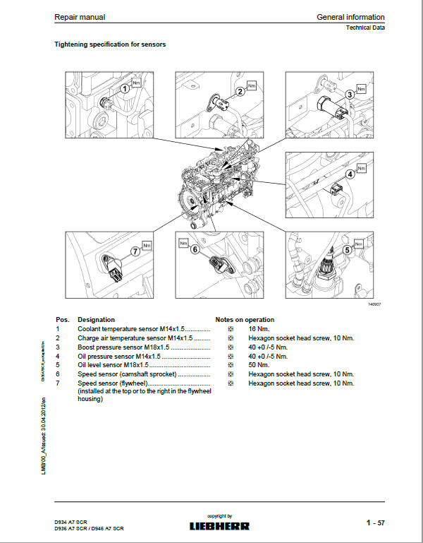
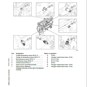
Tightening specification for sensors
Installation instruction for cable harness
Installation instruction for throttle valve
Tightening specification for heater flange
Tightening specification for idler
Tightening specification for air compressor gear
Installation instruction for coolant pump
Tightening specification for exhaust manifold (D934)
Tightening specification for thermal protection plate (D934)
Tightening specification for exhaust manifold (D936 / D946)
Tightening specification for thermal protection plate (D936 / D946)
Tightening specification for coolant pump
Tightening specification for turbocharger and flange on turbocharger
Tightening specification for generator belt pulley
Tightening specification for flywheel housing
Tightening specification for flywheel
Tightening specification for control unit-mount
Tightening specification for power take-off
Tightening specification for SCR module (installed machine side)
1.7.10 Cleaning agents, thread-locking adhesives and greases
1.8 Representations of the engine and engine components
1.8.1 Gear train (D934)
1.8.2 Gear train (D936 / D946)
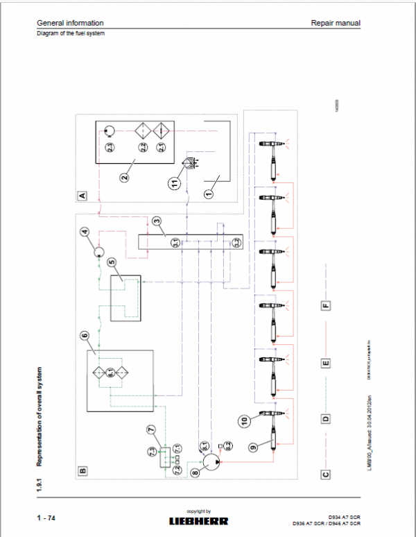
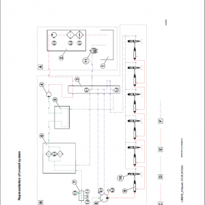
1.9 Diagram of the fuel system
1.9.1 Representation of overall system
1.10 Diagram of lube oil system
1.11 Diagram of coolant system
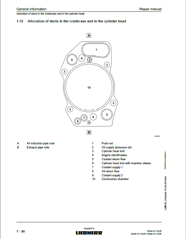
1.12 Allocation of ducts in the crankcase and in the cylinder head
1.13 Tools
1.13.1 Special tools
Lifting beam
Engine assembly stand
Lifting device for flywheels (SAE0, SAE1, SAE2)
Turning gears
Mounting bolts
Angle of rotation devices
Torx tools
Installing and dismantling the cylinder liner
Checking excess length of the cylinder liners
Installing and dismantling the front crankshaft seal
Installing and dismantling the crankshaft
Installing and dismantling the piston with connecting rod and piston rings
Installing and dismantling the piston rings
Installing and dismantling valve stem seals, valve springs and valves
Installing and dismantling the counterbalancing shafts
Dismantling and installing the camshafts
Installing and dismantling the injection lines
Installing and dismantling the pressure pipe tube and injector
Installing and dismantling the flywheel
Installing and dismantling the rear crankshaft seal
Target group
This repair manual has been compiled specifically for the mechanics and the workshop personnel of the LIEBHERR Owners and LIEBHERR subsidiaries, whose task it is to ensure that the diesel engines are in perfect working order.
Be the first to review “Liebherr D934 A7 SCR, D936 A7 SCR, D946 A7 SCR Diesel Engine Service Repair Manual”
You must be logged in to post a review.
Reviews
There are no reviews yet.