
Liebherr D934 A7 DPF, D936 A7 DPF, D946 A7 DPF Diesel Engine Service Repair Manual
$26.00
Manual Included:
- Service Repair Manual: 126 Pages
Specifications:
- Brand: Liebherr
- Model: D934 A7 DFP, D936 A7 DFP, D946 A7 DFP
- Type: Engine
- Manuals: Service Repair Manual
- Publication Numbers: 11160823
- Language: English
- Format: PDF
- Description
- Reviews (0)
Description
Table of Content of the Engine Repair Service Manual
1 General Information
-
Structure of this Manual
-
Important Notes Within This Manual
-
Designation of Activity-Related Notes on Safety
-
Further Designations
-
-
Symbols in This Manual
-
Notes on Safety
-
General Notes on Safety
-
Preventing Injury to Persons
-
Preventing Damage to Property
-
-
Notes Regarding Working on the Fuel System and Injection System
-
General Notes on Safety
-
Preventing Injury to Persons
-
Preventing Damage to Property
-
-
Technical Data
-
Engine in General
-
Standard Tightening Torques for Screw Connections
-
Standard Torques for Locking Screws and Banjo Bolts
-
Standard Torques for Metric Threaded Unions
-
Standard Torques for Imperial Threaded Unions
-
Standard Torques for Cutting Ring Threaded Unions
-
Standard Torques for Triple Lock Threaded Unions
-
Standard Torques for VSTI Screw Plugs
-
Special Torques, Tightening Specifications, Installation Specifications and Installation Instructions
-
General Notes
-
Tightening Specification for Main Bearing
-
Tightening Specification for Aggregate Carrier
-
Tightening Specifications for Piston Cooling Nozzle
-
Tightening Specification for Final Regulating Valve and Cold Start Valve
-
Tightening Specification for Oil Intake
-
Tightening Specification for Oil Drain Valve
-
Tightening Specification for Oil Sump (D934)
-
Tightening Specification for Oil Sump (D936 / D946)
-
Tightening Specification for Crankshaft Accessories
-
Tightening Specification for Connecting Rod
-
Tightening Specification for Cylinder Head
-
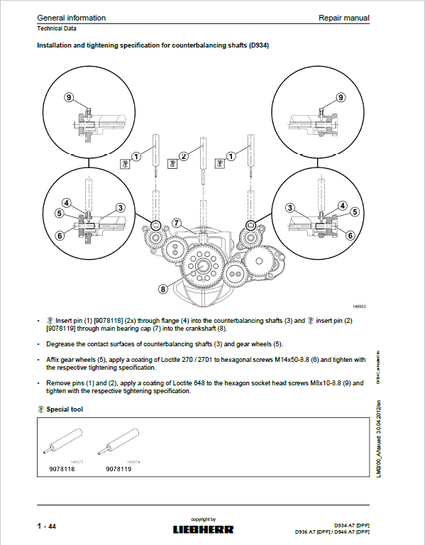
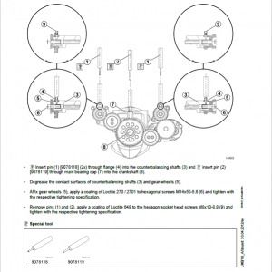
Installation and Tightening Specification for Counterbalancing Shafts (D934)
-
Tightening Specification for Rocker Arm Support
-
Installation and Tightening Specification for Camshaft
-
Tightening Specification for Camshaft Sprocket on Aggregate Carrier and Flywheel Side
-
Tightening Specification for Oil Cooler
-
Tightening Specification for Oil Cooler Housing (D934)
-
Tightening Specification for Oil Cooler Housing (D936 / D946)
-
Tightening Specification for Fitting in Oil Filter Bracket
-
Installation and Tightening Specification for High-Pressure Pump
-
Installation and Tightening Specification for Injector and Pressure Pipe Tube
-
Installation Instruction for Cable Harness on Injector
-
Tightening Specification for Sensors
-
Installation Instruction for Cable Harness
-
Installation Instruction for Air Intake
-
Installation Instruction for Intercooler
-
Tightening Specification for Heater Flange
-
Tightening Specification for Idler
-
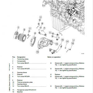
Tightening Specification for Air Compressor Gear
-
Installation Instruction for Coolant Pump
-
Installation Instruction for Thermostat Housing and Thermostat (3rd Thermostat)
-
Installation Instruction for Thermostat Housing and Thermostat
-
Installation Instruction for Water Manifold
-
Installation Instruction for Charge Air Duct
-
Installation Instruction for Exhaust Stack
-
Tightening Specification for Coolant Pump
-
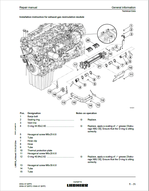
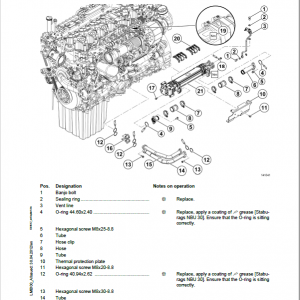
Installation Instruction for Exhaust Gas Recirculation Module
-
Tightening Specification for Exhaust Gas Recirculation
-
Installation Instruction for Exhaust Gas Recirculation Housing
-
Tightening Specification for Thermal Protection Plate
-
Installation Instruction for Actuator
-
Installation Instruction for Turbocharger (Low Pressure)
-
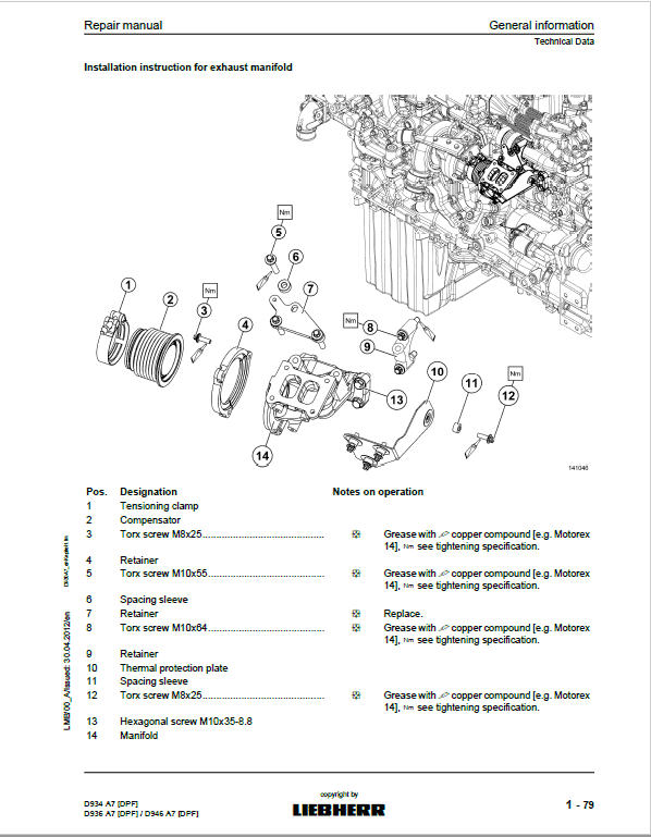
Installation Instruction for Exhaust Manifold
-
Installation Instruction for Exhaust Manifold
-
Tightening Specification for Exhaust System
-
Installation Instruction for Turbocharger (High Pressure)
-
Tightening Specification for Generator Belt Pulley
-
Tightening Specification for Flywheel Housing
-
Tightening Specification for Flywheel
-
Tightening Specification for Mounting of Control Units and Mounting of Sensor
-
Tightening Specification for Power Take-Off
-
Installation and Tightening Specification for Fuel Line Between Injection and Dosing Unit (D936)
-
Installation and Tightening Specification for Injection Unit
-
Installation and Tightening Specification for Dosing Unit
-
Tightening Specification for Particle Filter (Installed on the Machine Side)
-
-
Cleaning Agents, Thread-Locking Adhesives and Greases
-
-
Representations of the Engine and Engine Components
-
Gear Train (D934)
-
Gear Train (D936 / D946)
-
-
Diagram of the Fuel System
-
Representation of Overall System
-
-
Diagram of Lube Oil System
-
Diagram of Coolant System
-
Allocation of Ducts in the Crankcase and in the Cylinder Head
-
Tools
-
Special Tools
-
Lifting Beam
-
Engine Assembly Stand
-
Lifting Device for Flywheels (SAE0, SAE1 and SAE2)
-
Turning Gears
-
Mounting Bolts
-
Angle of Rotation Devices
-
Torx Tools
-
Installing and Dismantling the Cylinder Liner
-
Checking Excess Length of the Cylinder Liners
-
Installing and Dismantling the Front Crankshaft Seal
-
Installing and Dismantling the Crankshaft
-
Installing and Dismantling the Piston with Connecting Rod and Piston Rings
-
Installing and Dismantling the Piston Rings
-
Installing and Dismantling Valve Stem Seals, Valve Springs and Valves
-
Installing and Dismantling the Counterbalancing Shafts
-
Dismantling and Installing the Camshafts
-
Installing and Dismantling the Injection Lines
-
Installing and Dismantling the Pressure Pipe Tube and Injector
-
Installing and Dismantling the Flywheel
-
Installing and Dismantling the Rear Crankshaft Seal
-
-
Be the first to review “Liebherr D934 A7 DPF, D936 A7 DPF, D946 A7 DPF Diesel Engine Service Repair Manual”
You must be logged in to post a review.

Reviews
There are no reviews yet.