
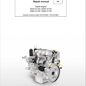
Liebherr D934 A7–04, D944 A7–04, D936 A7–04, D946 A7–04 Engine Service Repair Manual
$36.00
Manual Included:
- Service Repair Manual: 326 Pages
- Operators Manual: 102 Pages
Specifications:
- Brand: Liebherr
- Model: D934 A7–04, D944 A7–04, D936 A7–04, D946 A7–04
- Type: Engine
- Manuals: Service Repair Manual & Operators Manual
- Language: English
- Format: PDF
- Description
- Reviews (0)
Description
Table of Content D934 A7-04, D936 A7-04, D944 A7-04, D946 A7-04 Service Manual
1 General information
1.2 Important notes in this manual
1.2.1 Identification of operational safety instructions
1.2.2 Additional identifications
1.3 Safety instructions
1.3.1 General safety instructions
1.3.2 Preventing personal injuries
1.3.3 Preventing property damage
1.4 Safety instructions for working on the fuel and injection system
1.4.1 General safety instructions
1.4.2 Preventing personal injuries
1.4.3 Preventing property damage
1.5 Safety instructions for working on the exhaust after-treatment system (SCR system)
1.5.1 Reducing agent
1.5.2 General safety instructions
1.5.3 Preventing personal injuries
1.5.4 Preventing property damage
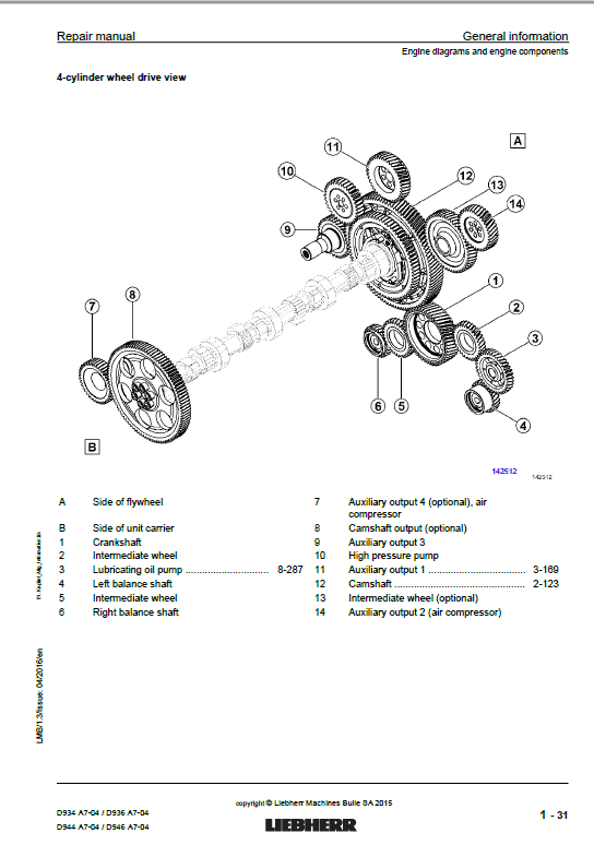
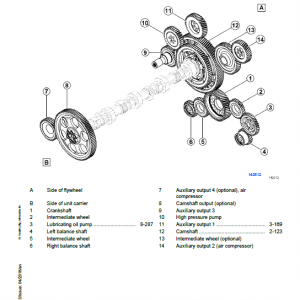
1.6 Engine diagrams and engine components
1.7 Technical data
1.7.1 Engine, general
1.7.2 Standard torques for screw connections
1.7.3 Standard torques for screw plugs and banjo screws
1.7.4 Standard torques for metric screw fittings
1.7.5 Standard torques for imperial screw fittings
1.7.6 Standard torques for cutting ring screw fittings
1.7.7 Standard torques for triple-lock screw fittings
1.7.8 Standard torques for VSTI screw plugs
1.8 Special torques, tensioning instructions, instructions for mounting and installation instructions
1.8.1 Cleaning and locking agents, greases
1.8.2 Special torques for cylinder head engine control unit and valves
1.8.3 Special torques for the engine
1.8.4 Special torques for fuel and injection system
1.8.5 Special torques for charge air and exhaust system
1.8.6 Special torques for the electrical system
1.8.7 Special torques for the lubrication system
1.8.8 Special torques for the auxiliary output, air compressor
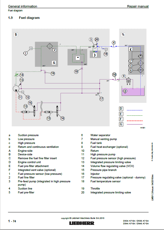
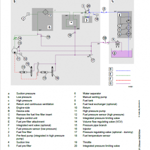
1.9 Fuel diagram
1.10 Lubricating oil diagram
1.11 Coolant diagram
1.11.1 Coolant diagram, general overview
1.11.2 Coolant circuit, engine
1.12 Assigning the channels in the crankcase and the cylinder head
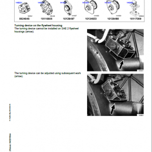
1.13 Transport device and fastening parts
1.13.1 Removing and installing the transport device and fastening parts
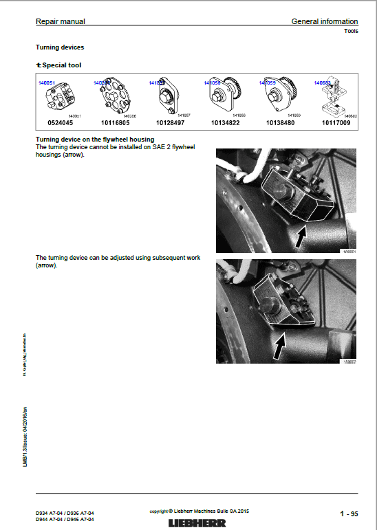
1.14 Tools
1.14.1 Special tools
2 Cylinder head, engine control unit and valves
2.1 Removing and installing the cylinder head cover
2.2 Removing and installing the rocker arm bracket and push rods
2.3 Removing and installing the valve bridge (engines with and without ABS)
2.4 Removing and installing the cylinder head
2.5 Removing and installing the injector sleeve
2.6 Removing and installing the valve stem seal, valve springs, valves
2.6.1 Remove
2.6.2 Installing
2.6.3 Removing and installing the valve stem seal without removing the cylinder head
2.7 Removing and installing the roller tappet (valve controller)
2.8 Removing and installing the camshaft
2.8.1 Remove
2.8.2 Installing
3 Driving gear
3.1 Removing and installing the piston with crank and piston rings
3.1.1 Overview
3.1.2 A: Removing and installing the piston with crank from the engine
3.1.3 B: Removing and installing the piston rings
3.1.4 C: Removing and installing the pistons
3.2 Removing and installing the cylinder liner
3.2.1 Checking the cylinder liners’ projection
3.3 Removing and installing the crankshaft attachments
3.4 Removing and installing the front crankshaft seal
3.4.1 General instructions
3.4.2 Remove
3.4.3 Installing
3.5 Removing and installing the unit carrier
3.6 Removing and installing the flywheel
3.6.1 Remove
3.6.2 Installing
3.6.3 Removing and installing the starting gear ring
3.7 Removing and installing the rear crankshaft seal
3.7.1 General instructions
3.7.2 Remove
3.7.3 Installing
3.8 Removing and installing the flywheel housing
3.9 Removing and installing the top right intermediate wheel
3.10 Removing and installing the top middle intermediate wheel
3.11 Removing and installing the crankshaft
3.11.1 Remove
3.11.2 Installing
4 Fuel and injection system
4.1 Removing and installing the fuel lines
4.2 Removing and installing the injection lines
4.2.1 Removing fuel lines
4.2.2 Installing fuel lines
4.3 Removing and installing the pressure pipe branch and injector
4.3.1 Removing the pressure pipe branch and injector
4.3.2 Installing the pressure pipe branch and injector
4.4 Removing and installing the fuel fine filter with console
4.4.1 Installing and filling the fuel fine filter
4.5 Removing and installing the fuel high pressure pump
4.5.1 Removing and installing the fuel pre-feed pump
4.5.2 Removing and installing the suction throttle valve
4.6 Removing and installing the fuel high pressure pump drive
5 Belt drive
5.1 Overview of belt drives
5.2 Removing and installing the belt drive cover
5.3 Removing and installing the V-ribbed belt tensioning device
5.4 Removing and installing the V-ribbed belt deflection roller
5.5 Removing and installing belt drive II (air conditioning compressor variant II)
5.6 Removing and installing belt drive III (fan drive)
6 Charge air and exhaust system
6.1 Removing and installing the air intake pipe
6.2 Removing and installing the air intake attachment
6.3 Removing and installing the clock valve
6.4 Removing and installing the connecting line (turbocharger – charge air cooler)
6.4.1 Connecting line (turbocharger – charge air cooler) variant 1
6.4.2 Connecting line (turbocharger – charge air cooler) variant 2
6.4.3 Connecting line (turbocharger – charge air cooler) variant 3
6.5 Removing and installing the heat protection plate
6.6 Removing and installing the exhaust pipe
6.6.1 Dismantling and assembling the 6-cylinder exhaust pipe
6.7 Removing and installing the exhaust branch
6.8 Removing and installing the intake branch
6.9 Removing and installing the turbocharger
6.10 SCR exhaust after-treatment system
6.10.1 SCR functional overview
6.10.2 SCR module
6.10.3 Reducing agent pump
6.10.4 Heating system for reducing agent lines
6.10.5 Air compressor
6.10.6 Reducing agent extraction module
6.10.7 Mixing section, installing the injector and the high temperature sensor in the mixing section
6.10.8 Sensor section
6.10.9 Removing and installing sensors
6.10.10 WABCO water valve
6.11 Troubleshooting in SCR system
7 Electrical system
7.1 Removing and installing the heating flange
7.2 Removing and installing the alternator
7.3 Removing and installing the starter
7.4 Removing and installing sensors
7.4.1 Instructions for mounting sensors
7.5 Removing and installing the engine control unit
7.5.1 Instructions for dismounting the engine control unit
7.5.2 Instructions for mounting the engine control unit
7.6 Replacing the cable harness
7.6.1 Preparation
7.6.2 Removing the cable harness
7.6.3 Installing the cable harness
8 Lubrication system
8.1 Replacing the oil filter
8.2 Removing and installing the crankcase ventilation
8.3 Removing and installing the oil return line (crankcase ventilation)
8.4 Removing and installing the oil dipstick and guiding pipe
8.5 Removing and installing the oil filler neck
8.6 Removing and installing the single-piece oil pan
8.7 Removing and installing the connecting piece (oil pan – crankcase)
8.8 Removing and installing the oil cooler housing with oil cooler
8.8.1 Dismantling and assembling the oil cooler housing with oil cooler
8.8.2 Removing and installing the cold start valve from/in the oil cooler housing
8.9 Removing and installing the oil pressure pump
8.10 Removing and installing the oil extraction pump (D936, D946)
8.10.1 Removing and installing the suction and feed lines for the oil extraction pump (D936, D946)
8.11 Removing and installing the locking pieces for the oil extraction pump (D936, D946)
8.12 Removing and installing the piston cooling injector
8.13 Removing and installing the end control valve
9 Cooling system
9.1 Removing and installing the coolant ventilation line
9.2 Removing and installing the coolant pump
9.3 Removing and installing the coolant manifold
9.4 Removing and installing the thermostat housing and the thermostat
10 Auxiliary output, air compressor and air conditioning compressor
10.1 Overview of auxiliary outputs
10.2 Removing and installing auxiliary output 1
10.3 Removing and installing auxiliary output 2
10.4 Removing and installing auxiliary output 3
10.5 Removing and installing auxiliary output 4
10.6 Removing and installing the air compressor
10.7 Removing and installing the switchable auxiliary output on the flywheel housing
10.7.1 Remove
10.7.2 Installing
10.8 Dismantling the switchable auxiliary output for the spool repair kit
10.9 Dismantling and assembling the switchable auxiliary output bearing housing
10.10 Installing and removing the air conditioning compressor, variant 1
10.11 Installing and removing the air conditioning compressor, variant 2
11 Appendix
11.1 Symbols in this manual
11.2 Abbreviations used
Be the first to review “Liebherr D934 A7–04, D944 A7–04, D936 A7–04, D946 A7–04 Engine Service Repair Manual”
You must be logged in to post a review.
Reviews
There are no reviews yet.