
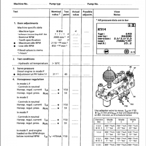
Liebherr D834 A7 Diesel Engine Service Repair Manual
$42.00
Manual Included:
- Service Repair Manual: 402 Pages
Specifications:
- Brand: Liebherr
- Model: D834 A7
- Type: Diesel Engine
- Manuals: Service Repair Manual
- Language: English
- Format: PDF
- Description
- Reviews (0)
Description
Table of Content (D834 A7 – Repair Manual)
Title
Repair instruction
Foreword / Imprint
Introduction
Explanation of symbols
Warnings
Tips and Recommendations
General Information
INH
Introduction
Regulations for avoiding health and environmental risks
Emergency drive program for engines with electronic control units
Installation information
Installation of screws and nuts
Engine Presentation
Explanation of type plate
Explanation of model designation
Specifications
D834 A7
Engine Description
Engine description
Cooling System Overview
Cooling system
Coolant Manifold
Additional work
Important information
Thermostat
Technical data
Important information
Remove coolant lines
Remove coolant outlet pipe
Remove thermostat
Remove thermostat housing
Install thermostat housing
Install thermostat
Install coolant outlet pipe
Install coolant lines (thermostat housing)
Mount coolant lines
Coolant Pump
Technical data
Important information
Remove V-ribbed belt
Remove coolant lines
Remove V-ribbed belt pulley
Remove coolant pump
Mount V-ribbed belt
Install coolant lines (to air compressor / engine)
Install V-ribbed belt
Coolant Pump – Overhaul
Additional work
Technical data
Important information
Special tools
Determine impeller installation dimension
Measure installed dimension
Remove coolant pump hub
Remove retaining ring
Remove impeller
Remove rotary seal
Install bearing
Install retaining ring
Press-fit hub, coolant pump
Install rotary seal
Check installed dimension
Hydraulic press-fitting of impeller
Check dimension, impeller to coolant pump housing
Mounted Aggregates – Overview
Mounted aggregate
Power Take-off
Additional work
Technical data
Important information
V-ribbed belt pulley, remove
Remove power take-off
Install power take-off
Mount V-ribbed belt
Air Compressor
Additional work
Technical data
Important information
Special tools
Remove air compressor suction line
Remove vent line for engine venting
Dismount oil return line
Remove bracket (holder)
Remove coolant lines
Remove heat shield, exhaust manifold (cyl. 3 and 4)
Swing away oil separator
Remove heat shield, exhaust manifold
Dismount exhaust manifold
Remove formed oil return pipe (air compressor)
Remove air compressor
Install air compressor
Install exhaust manifold / heat shield / oil separator back
Install coolant lines and vent lines
Air Compressor – Overhaul
Additional work
Technical data
Important information
Special tools
Remove compressor connections
Install disassembly tool on compressor
Dismount drive gear
Mount drive gear
Remove tool
Reconnect compressor
Belt Drive – Alternator
Technical data
Remove alternator V-ribbed belt
Remove coolant-compressor belt tensioner
Install coolant-compressor belt tensioner
Install alternator V-ribbed belt
Belt Drive – Kaemiko-AB
Technical data
Important information
Special tools
Install engine cranking device
Remove V-ribbed belt
Remove deflection pulley
Install deflection pulley
Install V-ribbed belt
Remove assembly tool
Remove engine cranking device
Belt Drive – Kaemiko-C
Important information
Special tools
Install engine cranking device
Remove V-ribbed belt (coolant compressor)
Remove deflection pulley
Install deflection pulley
Install V-ribbed belt (coolant compressor)
Remove assembly tool
Remove engine cranking device
Alternator (Generator)
Additional work
Technical data
Important information
Special tools
Disconnect alternator electrical connections
Remove alternator
Remove support / carrier
Remove V-ribbed belt pulley
Install V-ribbed belt pulley
Tighten fixing nut
Install support and retainer
Install alternator
Connect electrical connections
Starter
Technical data
Important information
Special tools
Remove starter
Install starter
Refrigerant / A/C Compressor
Additional work
Technical data
Important information
Special tools
Close coolant connections
Remove A/C compressor
Remove A/C compressor bracket
Install A/C compressor and remove sealing plugs
CRS – Common Rail System (Overview)
Injectors and Pressure Pipe
Remove / install injectors and pressure pipe
Technical data
Important information
Special tools
Remove high-pressure lines and pressure pipe
Remove rail pressure sensor and pressure limiting valve
Install injectors and pressure pipe
High-pressure Pump
Remove / install high-pressure pump
Technical data
Important information
Special tools
Remove high-pressure pump
Adapt drive gear, high-pressure pump
Install high-pressure pump
Connect fuel and high-pressure lines
Flame Start System
Remove / install flame start system
Technical data
Important information
Special tools
Remove flame glow plug and solenoid valve
Install flame start system and fuel line
Charging (Turbocharging)
General information on charging
Charge-air Pipes
Remove / install charge-air pipes
Additional work
Technical data
Important information
Remove charge-air manifold (compressor side)
Remove charge-air inlet housing
Remove charge-air manifold
Remove charge-pressure sensor
Install charge-pressure sensor
Install charge-air pipes and manifolds
Exhaust Turbocharger
Exhaust turbocharger – remove / install
Technical data
Important information
Special tools
Remove charge-air pipe
Remove engine-vent line
Remove oil return line
Remove holders and coolant lines
Remove heat shields and exhaust manifold
Remove intake neck
Remove exhaust turbocharger
Install exhaust turbocharger and timing valve
Connect wastegate control hose
Install exhaust manifold and heat shields
Fill turbocharger with oil
Install coolant and oil lines
Install charge-air pipe
Intake / Exhaust System
System overview
Air Distribution Pipe
Remove / install air distribution pipe
Additional work
Technical data
Important information
Special tools
Remove charge-air manifold (compressor side)
Remove charge-air inlet housing
Remove fuel line (high-pressure pump ↔ air distribution pipe)
Remove high-pressure line (HP pump ↔ pressure pipe)
Remove high-pressure lines (cyl. 1–4)
Remove pressure pipe
Remove temperature sensor
Remove air distribution pipe
Install air distribution pipe and all removed lines / sensors
EGR Module
EGR module – remove / install
Additional work
Technical data
Important information
Remove coolant lines and temperature sensor
Remove EGR module and EGR closing flap
Install EGR module, EGR flap, coolant lines, sensor, and lifting eye
Exhaust Manifold
Exhaust manifold – remove / install
Additional work
Technical data
Important information
Special tools
Remove heat shield, oil separator, vent line
Remove exhaust manifold
Install exhaust manifold and refit removed parts
Cylinder Head (Overview)
Rocker Arm Gear (Kipphebelwerk)
Remove / install rocker arm gear
Additional work
Technical data
Important information
Remove cylinder head cover
Remove rocker arm shaft / gear
Install rocker arm gear
Install cylinder head cover
Rocker Arm Gear – Overhaul
Additional work
Technical data
Important information
Special tools
Disassemble rocker arm gear
Assemble rocker arm gear
Cylinder Head – Remove / Install
Additional work
Technical data
Important information
Special tools
Remove valve bridges and push rods
Loosen cylinder head bolts in sequence
Remove cylinder head and gasket
Install new gasket and cylinder head
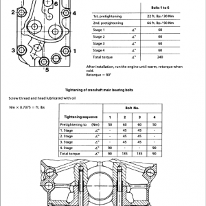
Tightening sequence and tightening torques
Install valve bridges and push rods
Valve Clearance
Check / adjust valve clearance
Technical data
Important information
Special tools
Install engine cranking device
Set engine to adjustment position
Check / adjust inlet valve
Check / adjust exhaust valve
Install cylinder head cover
Remove cranking device
Valve Stem Seals
Remove / install valve stem seals
Additional work
Technical data
Important information
Special tools
Set engine to TDC
Remove valve springs and keepers with special tool
Remove valve stem seals
Install valve stem seals and springs
Refit valve bridges and push rods
Remove cranking device
Valve Drive
General description of valve train
Camshaft
Remove / install camshaft
Additional work
Technical data
Important information
Special tools
Remove flange and install puller
Remove camshaft and tappets
Install tappets and camshaft
Check camshaft end float
Install camshaft gear
Camshaft Bearings
Remove / install camshaft bearings
Additional work
Important information
Special tools
Removal sequence for camshaft bearings
Use centering discs in bearing seats
Install camshaft bearings in correct order
Check oil bores
Timing Gears – Overview
Timing Gears – Remove / Install
Additional work
Technical data
Special tools
Remove intermediate gears
Fix crankshaft gear
Install engine cranking device
Align timing marks
Remove / install oil-pump drive gear
Remove / install camshaft gear
Remove / install crankshaft gear
Recheck overlap marking and remove cranking device
Engine Lubrication (Overview)
Oil Cooler
Remove / install oil cooler
Technical data
Important information
Drain coolant
Remove oil cooler housing and cooler
Install oil cooler and housing
Install locking screw
Oil Pan
Remove / install oil pan
Technical data
Consumables
Important information
Special tools
Remove oil return line and formed oil return pipe
Remove lower oil pan
Remove oil suction pipe, dipstick, filler pipe
Remove upper oil pan
Install upper and lower oil pan
Refit oil return line and formed pipe
Oil Pump
Remove / install oil pump
Additional work
Technical data
Important information
Special tools
Unscrew oil-pump fixing screws
Remove oil pump
Check gearwheel axial play
Disassemble / assemble oil pump
Install oil pump and tighten screws
Oil Injection Nozzles
Remove / install oil spray nozzles
Additional work
Technical data
Important information
Special tools
Remove oil spray nozzles
Install oil spray nozzles and align
Crank Drive
General description of crank drive
Vibration Damper
Remove / install vibration damper
Additional work
Technical data
Important information
Special tools
Install engine cranking device
Remove V-ribbed belt pulley
Loosen and remove vibration damper
Install and tighten vibration damper
Install V-ribbed belt pulley
Remove cranking device
Flywheel
Remove / install flywheel
Technical data
Important information
Special tools
Remove flywheel with guide mandrel
Check flywheel run-out
Install flywheel and tighten screws in sequence
Remove / install starter ring gear
Piston and Connecting Rod
Remove / install piston with conrod
Additional work
Technical data
Important information
Special tools
Remove conrod bearing cap
Remove piston and pin
Check piston rings, ring end gap, pin bore, and conrod bore
Install rings, pin, piston, and bearing cap
Check piston protrusion
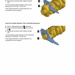
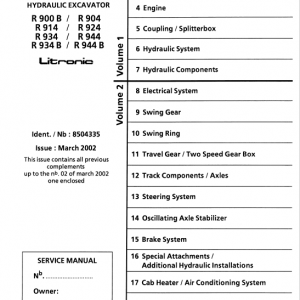
Crankshaft
Remove / install crankshaft
Additional work
Technical data
Important information
Special tools
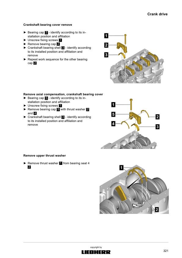
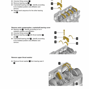
Remove bearing caps and thrust washers
Remove crankshaft
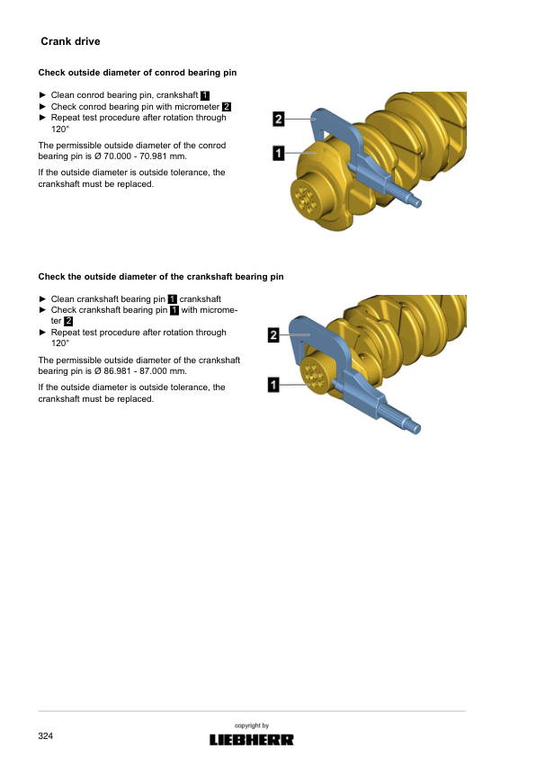
Inspect crankshaft and bearings
Install crankshaft, thrust washers, and caps
Tighten bearing cap screws
Check crankshaft end play
Crankshaft Sealing Rings – Front
Remove / install front crankshaft seal
Additional work
Important information
Special tools
Remove seal with special tool
Press in new seal to specified position
Crankshaft Sealing Rings – Rear
Remove / install rear crankshaft seal
Additional work
Important information
Special tools
Remove seal with special tool
Press in new seal to specified position
Crankcase
Crankcase – remove / install components
Crankcase Ventilation
Remove / install crankcase breather
Additional work
Important information
Special tools
Remove oil-air separator
Remove vent line and oil return in oil pan
Install all components in reverse order
Flywheel Housing
Remove / install flywheel housing
Additional work
Important information
Remove lifting eye
Remove housing
Install housing and lifting eye
Timing Case Cover
Remove / install timing case cover
Additional work
Technical data
Important information
Special tools
Remove cover and seal
Install new seal and cover
Timing Case
Remove / install timing case
Additional work
Important information
Remove lower fixing screws
Remove timing case and seal
Install timing case and tighten lower screws
Technical Data
Tightening torques
Locking screws
Cooling system data
Mounted aggregates
Common rail system data
Charging data
Intake / exhaust system data
Cylinder head data
Timing gear data
Engine lubrication data
Crank drive data
Conrod and piston data
Crankcase data
Assembly tightening torques
Test and setting values
Special Tools – Overview
Special tools
Special tools with order number
Lifting devices
Engine stand and expansions
Be the first to review “Liebherr D834 A7 Diesel Engine Service Repair Manual”
You must be logged in to post a review.
Reviews
There are no reviews yet.