
Liebherr A942 Hydraulic Excavator Service Repair Manual
$42.00
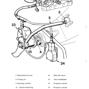
Manual Included:
PIN/Type – 159, 312
- Service Repair Manual: 1264 Pages
Specifications:
- Type: Excavator
- Model: A942
- PIN/Type: 159, 312
- Manuals: Repair Manual
- Language: English
- Format: PDF
- Description
- Reviews (0)
Description
Table of Content – Liebherr A942 Hydraulic Excavator Type 159, 312 Manual
- Book I A 900 – A 942
- Titel
- Introduction
- Index
- 1.2 Tables / Data / Torque
- 1.2.00 Description of metric bolts / Wrench sizes
- 1.2.01 Tightening torques bolts grade 8.8
- 1.2.02 Tightening torques bolts grade 10.9
- 1.2.03 Tightening torques bolts grade 12.9
- 1.2 05 Tightening torques for Durlock bolts grade 12.9
- 1.2.08 1.2.01 Tightening torques for Ermeto connections
- 1.2.10 Hole diameters for tapping standard metric thread
- 1.2.11 Hole diameters for tapping fine metric thread
- 1.2.15 ISO – Tolerances
- 1.2.20 Graphic sysmbols for hydraulic and pneumatic schematics
- 1.2.25 Graphic symbols for electrical diagrams
- 1.3 Tools / Special tools
- 1.3.00 Special tools for excavator
- 1.3.01 Mini text system
- 1.3.02 Pressure gauge
- 1.3.03 Flow meter
- 1.3.04 Test fitting
- 1.3.05 Spool clamp
- 1.3.06 Leakag plate
- 1.3.07 Spool travel measuring tool
- 1.3.08 Mounting tool for hydraulic cylinder, pumps and variable flow motors
- 1.3.09 Piston wrench
- 1.3.10 Piston nut wrench
- 1.3.12 Piston nut wrench
- 1.3.13 Test fitting for variable flow motors LMV
- 1.3.14 Removing device for transmital travel gear
- 1.4 Welding
- 1.4.01 Welding joints (Din 912)
- 1.5 Lubricants
- 1.5.01 Lubricant chart
- 1.5.02 Lubricating oil
- 2.0 Technical data / Inspection schedule
- 2.0.09 Technical data A 942
- 2.0.29 Inspection schedule A 942
- 2.1 Engine
- 2.1.01 Deutz Engine FL 912
- 2.1.02 Deutz Engine BFL 913/913 C
- 2.1.03 Deutz Engine FL 912
- 2.1.05 Liebherr Engine D 904 NA / D 904 T
- 2.1.06 Liebherr Engine D 906 NA / D 906 T
- 2.1.10 Sensor controlled low idle automatic
- 2.1.11 Sensor controlled low idle automaic
- 2.2 Swing gear / Swing brake
- 2.2.00 Torque value
- 2.2.03 Remove and install swing gear A/R 922 / R 932 / A/R 942
- 2.2.06 Disassembly / Assembly Instructions A/R 922 / R 932 / A/R 942
- 2.2.10 Swing brake / Maintenance and pressure settings
- 2.2.11 Swing brake / Remove and install
- 2.2.12 Swing brake / Funktion and operating / Bleed brake system
- 2.2.13 Repair and funktion od wheel cylinder with brake assembly
- 2.2.14 Repair and funktion of master cylinder
- 2.2.15 Swing brake troobleshooting
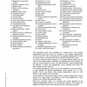
- 2.3 Hydraulic system
- 2.3.00 General information
- 2.3.01 Hydraulic system Pressure settings
- 2.3.08 Hydraulic system A 942
- 2.3.20 Pressure cut in / Lift
- 2.3.25 Front / Rear outriggers
- 2.3.30 Hydraulic servo system
- 2.3.32 Servo control with joystick
- 2.3.33 Servo control with foot pedal
- 2.3.40 Control valves
- 2.3.42 Control valves NG 16 / NG 22
- 2.3.50 Pressure relief valve – Direct acting
- 2.3.51 Pressure relief valve – Pilot operated
- 2.3.52 Pressure relief valve – Direct acting
- 2.3.53 Two way pressure relief valve
- 2.3.54 Suction valve
- 2.3.55 Thermostat valve
- 2.3.56 Flow divider
- 2.3.57 Restrictor check valve
- 2.3.58 Check valve with hydraulic release
- 2.3.59 Travel brake valve
- 2.3.62 Pressure relief valve with pressure cut in
- 2.3.84 Hydraulic pump LPVD (Liebherr) A 900 – A 942
- 2.3.88 Comparative flow test
- 2.3.89 Pump flow diagram
- 2.3.91 Hydraulic variable flow motor A6V (Hydromatik) A 900 – A 942
- 2.3.92 Hydraulic fixed displacement motor LMF (Liebherr) A 900 – A 942
- 2.4 Air pressure system
- 2.4.01 Pressure chart
- 2.4.20 Description and function of components
- 2.5 Rotary connection
- 2.5.02 Five-way air rotary connection
- 2.5.05 Oil rotary connection "Grau"
- 2.5.06 Oil rotary connection "Sigma"
- 2.5.08 Oil rotary connection "Liebherr"
- 2.6 Electrical system
- 2.6.01 General notes
- 2.6.02 Battery handling and maintenance
- 2.6.03 Starter
- 2.6.04 Alternator
- 2.6.05 Glow plug
- 2.7 Heater / Air conditioner
- 2.7.05 Engin oil heater
- 2.7.09 Cab heater installation A 942
- 2.7.10 Cab heater D1L
- 3.1 Two speed gear box
- 3.1.03 Remove and install / Gearbox
- 3.1.05 Diassembly and assembly / Two speed gear box
- 3.2 Front and real axle / Differential
- 3.2.01 Examples of Gleason gear
- 3.2.03 Removing and installation of front axle and differential
- 3.2.04 Removing and installation of rear axle and differential
- 3.2.05 Diassembly and assembly of differential – Carrier A1
- 3.2.06 Diassembly and assembly of differential – Carrier B
- 3.2.07 Diassembly and assembly of differential – Carrier C
- 3.2.10 Removing and installing / Front Axle
- 3.2.15 Removing and installing / Rear axle
- 3.3 Hydrostatic steering
- 3.3.01 Hydrostatic steering
- 3.3.05 Servostat
- 3.3.06 Flow indicator
- 3.4 Oscillating axle support
- 3.4.05 Oscillating axle support A 900 / A 942
- 3.5 Brakes
- 3.5.01 Pressure chart and instructions
- 3.5.02 Removing and installing – Four wheel brake
- 3.5.03 Construction and funktion of brakes / Bleeding
- 3.5.04 Function and adjusting – Hydraulic simplex brake
- 3.5.05 Function and repair of master cylinder
- 3.5.06 Troubleshooting
- 3.5.10 Function and instructions of brake (Pneumatic)
- 3.5.11 Function and adjusting of brake (Mechanical)
- 3.5.12 Troubleshooting
- 3.6 Swing ring
- 3.6 Remove and install swing ring
- 5.2 Special equipment / accessory kits
- 5.2.02 Overload warning device / General data
- 5.2.06 Overload warning device A/R 942
- 5.2.09 Hoist limit
- 5.2.10 Load check valve
- 5.2.11 Load check valve / Leckoil free
- 5.2.14 Attachment AS1 A/R 942
- 5.2.20 Attachment ASH A 942
- 5.2.30 Grapple Attachment
- 5.2.31 Grapple rotary device
- 5.2.32 Quick change coupling
- 5.2.34 Pin lock
- 5.2.35 Limit switch for industrial attachment
- 5.2.36 Crane attachment
- 5.2.38 Industrial crane
- 5.2.40 Adjustable cab
- 5.2.42 Dumping attachment
- 5.2.44 Dozer blade
- 5.2.46 Outrigger control
- 5.2.47 Slipring rotary connenction
- 5.2.50 Hydraulic hammer
- 5.2.51 Special attachment
- 5.3 Hydraulic cylinder
- 5.3.01 Hydraulic cylinder – Torque values
- 5.3.02 Hydraulic cylinder – Removing and installing
- 5.3.05 Hydraulic cylinder without cushioning
- 5.3.10 Hydraulic cylinder without/with cushioning
- 5.3.15 Hydraulic cylinder – Steering
- 5.3.25 Hydraulic cylinder A/R 942
Be the first to review “Liebherr A942 Hydraulic Excavator Service Repair Manual”
You must be logged in to post a review.

Reviews
There are no reviews yet.