

Liebherr A934 C, A934 C HD Litronic Hydraulic Excavator Operators Service Repair Manual
Price range: $20.00 through $50.00
Manual Included:
PIN/Type – 1006 & 1007
- Service Repair Manual: 2337 Pages
- Operators Manual: 328 Pages
- Operators Manual (High Rise Version): 272 Pages
PIN/Type – 1053
- Service Repair Manual: 2337 Pages
- Operators Manual: 263 Pages
PIN/Type – 1418 & 1419
- Service Repair Manual: 2337 Pages
- Operators Manual: 334 Pages
- Operators Manual (High Rise Version): 267 Pages
PIN/Type – 1498 & 1499
- Service Repair Manual: 1247 Pages
- Operators Manual: 282 Pages
Specifications:
- Type: Excavator
- Model: A934 C, A934 C HD Litronic
- PIN/Type: 1006 & 1007, 1053, 1418 & 1419, 1498 & 1499
- Manuals: Operators Manual, Repair Manual
- Language: English
- Format: PDF
- Description
- Additional information
- Reviews (0)
Description
Table of Content – Liebherr A934 C, A934 C HD Litronic Hydraulic Excavator Type 1006 & 1007 Manual
- Book I Chapter 1-7
- Document identification
- Preface
- Index
- Book II Chapter 8-19 (Page -1)
- Document identification
- Index
- 1 General Information
- 1.01 Standards and regulations
- 1.02 Changes and modifications to series
- 1.10 Safety instructions
- 1.21 Tightening torques for fittings
- 1.51 Fuels, lubricants and process chemicals
- 2 Tools
- 2.01 Special tools – general
- 2.02 Special tools for diesel engines
- 2.05 Special tools for hydraulic unit
- 2.06 Special tools for electrical equipment
- 2.07 Special tools for slewing gear mechanism
- 2.09 Special tools for axles (Kessler)
- 2.10 Stroke measuring device for control block
- 2.12 Assembly tools for hydraulic cylinders
- 2.13 Mounting device for piston rod bearings
- 2.14 Slotted nut wrench for slewing gear
- 2.15 Mounting device for multi-disc brake
- 2.20 Special tools, ERC cylinder
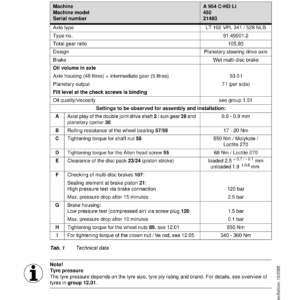
- 3 Technical Data / Maintenance Guidelines
- 3.05 Technical data A 934 C LI
- 3.06 Technical data A 934 C Li ERC
- 3.07 Technical data A 934 C HD LI
- 3.08 Technical data of A 934 C-HD LI ERC
- 3.09 Technical dataA 934 C HD LI Log Loader
- 3.11 Technical data
- 3.17 Inspection and maintenance schedule
- 3.29 Lubrication schedule for A 934 C Litronic Type 1006
- 3.30 Lubricating chart for A 934 C Litronic ERC type 1418
- 3.31 Lubrication schedule for A 934 C-HD Litronic Type 1007
- 3.32 Lubricating chart for A 934 C Litronic ERC type 1419
- 3.33 Lubrication Schedule A 934 C-HD Litronic log loader Type 1053
- 3.45 Adjustment protocol A 934 C Li
- 3.47 Adjustment protocol A 934 C LI ERC
- 3.50 Adjustment protocol A 934 C HD LI
- 3.52 Adjustment protocol A 934 C HD LI ERC
- 3.53 Adjustment protocol A 934 C HD LI log loader
- 3.69 Adjustment guidelines for the hydraulic system
- 3.70 Checking and adjusting tasks V4.7
- 3.71 Adjustment guidelines for hydraulic system
- 3.80 Checking and adjusting tasks V4.8.1
- 4 Engine
- 4.05 Bleeding the fuel system
- 4.10 Technical data of diesel engine
- 4.25 Liebherr diesel particle filter accessory kit
- 4.40 Datalogger version 2.3.00
- 4.41 Datalogger software version 2.3.09
- 5 Clutch / Splitterbox
- 5.10 Coupling
- 5.40 PVG 351 C pump distribution gear
- 6 Hydraulic System
- 6.50 Layout of hydraulic system type 1006/1007
- 6.55 Layout of hydraulic system type 194
- 6.60 Layout of hydraulic system type 450
- 6.70 Hydraulic schematic of working hydraulics type 1006/1007
- 6.72 Hydraulic schematic of working hydraulics type 1053 (log loader)
- 6.73 Hydraulic schematic of working hydraulics type 1053
- 6.75 Hydraulic diagram of working hydraulics
- 6.76 Hydraulic schematic of working hydraulics type 194
- 6.77 Hydraulic schematic of working hydraulics type 196 (log loader)
- 6.78 Hydraulic schematic of working hydraulics type 196
- 6.80 Hydraulic diagram of working hydraulics Typ 450
- 6.90 Hydraulic schematic of working hydraulics type 1418/1419
- 7 Hydraulic Components
- 7.05 Hydraulic pump removal, installation / Start-up
- 7.09 MKA 350 C 071 multiple circuit unit
- 7.11 Double variable-displacement pump DPVP 108
- 7.12 Double variable-displacement pump DPVP 108 in ERC models
- 7.13 LPV 165 variable-displacement pump
- 7.17 A4 VG variable-displacement pump
- 7.19 A10V028 ED variable-displacement pump
- 7.22 A6V regulating motor
- 7.25 FMF hydraulic fixed displacement motor
- 7.30 Hydraulic cylinder
- 7.33 Energy recuperation cylinder (ERC)
- 7.35 Hydraulic cylinder
- 7.42 Pilot control unit 1x (travelling foot pedal)
- 7.45 Control oil and regulation unit
- 7.50 Pilot control unit 4 x
- 7.54 Pilot control unit 2 x
- 7.60 M8 control valve block
- 7.70 Rotary connection 6 x
- 7.73 Rotary connection 7x
- 7.76 Rotary connection 9 x
- 7.81 Pilot-controlled primary pressure relief valve
- 7.83 Pilot-controlled pressure relief valve with additional pressure stage
- 7.85 Double stop valve for outrigger support
- 7.86 Pilot-controlled pressure relief valves with suction function
- 7.87 Secondary pressure relief valve, pilot-controlled
- 7.90 Suction valve
- 7.91 Restrictor check valve
- 7.93 Stop valves
- 8 Electrical System
- 8.01 Overview of electrical symbols
- 8.02 Notes regarding the electrical system
- 8.10 Layout of components
- 8.12 Electrical system in ERC models
- 8.25 Electrical system of basic machine A 934 C Li
- 8.44 Operating symbols on the operator's platform
- 8.50 BST excavator control (version 4…)
- 8.55 Monitoring display from version 4.8/V4.8.1
- 8.79 Control panel
- 8.80 Error code list
- 8.82 Slip ring contact
- 8.100 Electrical system – kits
- 9 Swing Gear
- 9.10 SAT slewing gear mechanism
- 9.20 Slewing gear brake / positioning brake
- 10 Swing Ring
- 10.10 Rotary connection
- 11 Two Speed Gear Box
- 11.10 2 HL 290 transmission
- 11.30 HBGV block for transmission
- 12 Axles / Gear Box
- 12.01 Tyres
- 12.03 Use of special tool (Kessler axles)
- 12.05 Introduction
- 12.07 Steering drive axle LT 71
- 12.08 Rigid axle D 71
- 12.16 Steering drive axle LT 81
- 12.18 Rigid axle D 81
- 12.25 Steering drive axle LT 81 for type 1053 (oscillating)
- 12.27 Steering drive axle LT 81 for type 1053 (rigid)
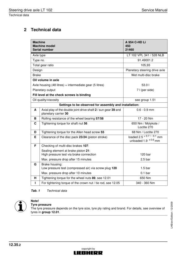
- 12.35 Steering drive axle LT 102
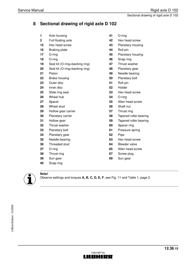
- 12.36 Rigid axle D 102
- 12.37 Differential D 108 for axles LT 102 / D102
- 12.50 D 51 auxiliary axle gear / spring pressure – multi disc brake
- 13 Steering
- 13.10 Hydraulic steering system, type 1006/1007
- 13.12 Hydraulic steering system, type 1053
- 13.14 Hydraulic steering system, type 196
- 13.16 Hydraulic steering system, type 194/450
- 13.18 Joystick steering
- 13.20 Steering valve
- 14 Oscillating Axle Stabilizer
- 14.10 Oscillating axle stabilization with automatic control
- 14.20 Support cylinder
- 15 Brake System
- 15.05 Operating pressures of the brake system
- 15.08 Hydraulic brake system, type 1006/1007/1053
- 15.10 Hydraulic brake system, type 194/196
- 15.12 Hydraulic brake system type 450
- 15.20 Compact brake block
- 16 Special Attachments / Accessory
- 16.08 Pipe fracture safety valves boom cylinders
- 16.10 Pipe fracture safety system of boom cylinder
- 16.12 Pipe fracture safety valve of stick cylinder
- 16.14 Pipe fracture safety valve of stick cylinder with double check valve
- 16.16 Pipe-fracture safety valve of hoist cylinder
- 16.18 Pipe fracture safety valve of stick cylinder
- 16.70 Individual outrigger support control
- 16.78 Hydraulic operator's cab elevation
- 16.80 Hydraulic operator's cab elevation system
- 16.82 Stick cylinder shut-down with proximity switch
- 16.84 Electronic stick cylinder shut-down
- 16.85 Lifting booms when closing grapple
- 16.86 Generator drive accessory kit
- 16.90 Generator conversion kit for LIKUFIX
- 16.95 Travel drive summation
- 17 Cab Heater / Air Conditioning System
- 17.40 Inspection and repair instructions for heating and air-conditioning system
- 17.50 Heating and air-conditioning system
- 18 Undercarriage / uppercarriage / attachments
- 18.01 Fixture of operator's cab elevation system
- 18.50 Repair instructions for lubrication hoses
- 19 Arrangement of Tanks
Additional information
| PIN Type | Type 1006 & 1007, Type 1053, Type 1418 & 1419, Type 1498 & 1499 |
|---|---|
| Manual | Service Repair Manual, Operators Manual, Operators Manual (High Rise Version) |
Be the first to review “Liebherr A934 C, A934 C HD Litronic Hydraulic Excavator Operators Service Repair Manual”
You must be logged in to post a review.
Reviews
There are no reviews yet.