
Liebherr A900 C ZW, A900 C ZW EDC Litronic Excavator Operators Service Repair Manual
Price range: $22.00 through $50.00
Manual Included:
PIN/Type – 729, 730, 931
- Service Repair Manual: 2035 Pages
- Operators Manual: 314 Pages
PIN/Type – 1030, 1031, 1032
- Service Repair Manual: 2035 Pages
- Operators Manual: 339 Pages
PIN/Type – 1033
- Service Repair Manual: 1975 Pages
- Operators Manual: 320 Pages
PIN/Type – 1384
- Service Repair Manual: 1975 Pages
- Operators Manual: 341 Pages
PIN/Type – 1385
- Service Repair Manual: 1975 Pages
- Operators Manual: 337 Pages
Specifications:
- Type: Excavator
- Model: A900 C ZW, A900 C ZW EDC Litronic
- PIN/Type: 729, 730, 931, 1030, 1031, 1032, 1033, 1384, 1385
- Manuals: Operators Manual, Repair Manual
- Language: English
- Format: PDF
- Description
- Additional information
- Reviews (0)
Description
Table of Content – Liebherr A900 C ZW, A900 C ZW EDC Litronic Excavator Type 1030, 1031, 1032 Manual
- Book I Chapter 1-8
- Titel
- Introduction
- Index
- Bock II Chapter 9-19
- Titel
- Index
- Bock II Chapter 9-19
- (1)
- Titel
- Index
- 1 General
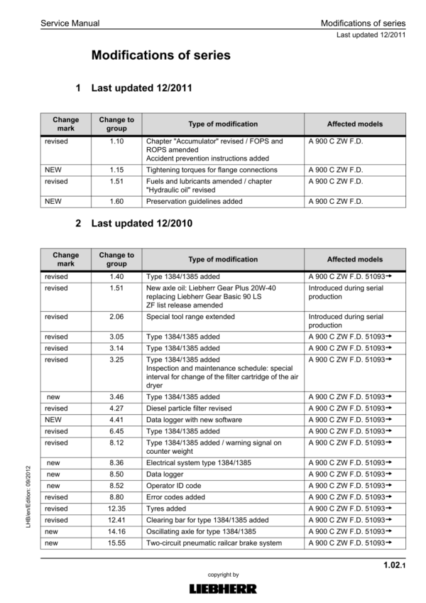
- 1.02 Modifications of series
- 1.10 Safety instructions
- 1.15 Tightening torques for flange connections
- 1.20 Tightening torques (WN 4037 K)
- 1.21 Tightening torques
- 1.22 Assembly instruction for hydraulilc cylinder WN 4121 C
- 1.24 Assembly instruction for hydraulic cylinder WN 4122 B
- 1.25 Tightening torques for piston rod bearing screws
- 1.40 Filling quantities
- 1.51 Fuels, lubricants and process chemicals
- 1.55 TE_ML05 lubricant list
- 1.56 TE_ML07 lubricant list
- 1.60 Conservation guidelines
- 2 Tools
- 2.01 Special tools – general
- 2.02 Special tools for diesel engines
- 2.03 Special tools for ZW equipment
- 2.05 Special tools for hydraulic system
- 2.06 Special tools for electrical equipment
- 2.07 Special tools for gears
- 2.08 Special tools for axles (ZF)
- 2.09 Special tools for axles (Kessler)
- 2.12 Assembly tools for hydraulic cylinders
- 2.13 Mounting device for piston rod bearings
- 2.14 Slotted nut wrench for slewing gear mechanism
- 2.15 Mounting device for multi-disk brake
- 3 Technical data / Maintenance instructions
- 3.05 Type overview of A 900 C ZW Litronic
- 3.12 Technical data
- 3.21 Inspection and maintenance schedule
- 3.30 Lubricating charts
- 3.35 Adjustment of ZW rail guide system
- 3.42 Adjustment protocol V4.7.2
- 3.43 Adjustment protocol V4.8.2
- 3.47 Checking and adjusting tasks
- 3.50 Maintenance schedule (scheduled inspection)
- 3.60 Warning and information signs on A 900 C ZW
- 4 Drive motor
- 4.05 Bleeding the fuel system
- 4.12 Technical data of diesel engines
- 4.25 Installation and check list
- 4.27 Liebherr diesel particle filter accessory kit
- 4.40 Datalogger version 2.3.00
- 4.41 Datalogger software version 2.3.09
- 5 Coupling / Pump distributor gear
- 5.10 Coupling
- 5.20 Pump distributor gear
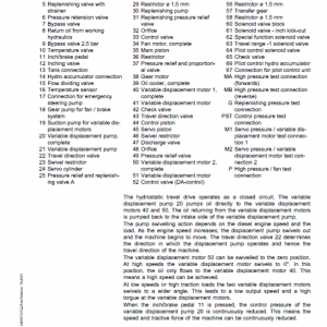
- 6 Hydraulic system
- 6.01 LSC system
- 6.31 Layout of hydraulic system
- 6.42 Hydraulic system A 900 C ZW, EDC 31354-
- 6.43 Hydraulic system A 900 C ZW EDC 50658
- 6.44 Hydraulic system A 900 C ZW EDC 53810
- 6.60 Function of ZW rail guide system
- 7 Hydraulic components
- 7.01 Hydraulic pumps – dismantling, installation and initial operation
- 7.05 Variable-displacement pump DPVP 108
- 7.10 Variable-displacement pump A10V0
- 7.20 FMF hydraulic fixed displacement motor
- 7.27 DMVA regulating motor (travel drive)
- 7.30 Hydraulic cylinder
- 7.31 Extension and retraction times of hydraulic cylinders
- 7.32 Hydraulic double plunger cylinder
- 7.41 Control oil and regulating unit
- 7.49 Pilot control unit 4x
- 7.51 Control block LSC
- 7.68 Leak oil check at control valve blocks
- 7.70 Rotary connection 6 x
- 7.75 Rotary connection 7x
- 7.80 Axle control block of the rail guide
- 7.95 Accumulator
- 7.85 Changeover travel / support
- 8 Electrical system
- 8.01 Overview of electrical symbols
- 8.02 Notes regarding the electrical system
- 8.12 Arrangement of components
- 8.32 Electrical system (basic machine)
- 8.34 Electical system with installation kits and wiring harnesses
- 8.44 Operating symbols on the operator's platform
- 8.50 Data logger
- 8.60 Electronically controlled working and travelling pedal
- 8.62 Calibration of the electric foot pedals
- 8.70 ZW monitoring display (TDS01)
- 8.72 Monitoring display from V.4.7.2
- 8.79 Control panel
- 8.80 Error code list
- 8.81 Emergency actuation (emergency operation)
- 8.82 Slip ring rotary connection
- 8.90 Resistance measurement
- 8.99 Self-holding mechanism for quick-change adapter locking
- 9 Slewing gear mechanism
- 9.10 Slewing gear mechanism
- 9.21 Slewing gear brake
- 9.25 Positioning slewing brake
- 10 Slewing ring
- 10.10 Slewing ring
- 11 Transmission
- 11.12 2 HL 290 transmission
- 11.35 HBGV block for transmission 2 HL 290
- 12 Axles / Rail guide system
- 12.35 Tyres
- 12.40 ZW rail guide
- 12.70 Conversion of rail gear for narrow gauge
- 12.90 Measuring of the wheel flange of the rail chassis
- 12.91 Measuring of tyre track width
- 12.95 Wear limits
- 13 Steering
- 13.10 Hydraulic steering system
- 13.25 Steering valve
- 13.33 Steering cylinder
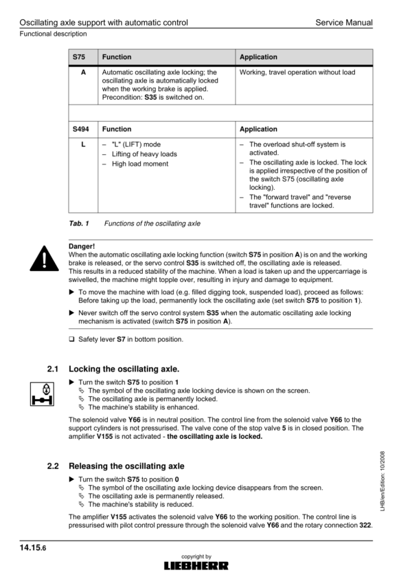
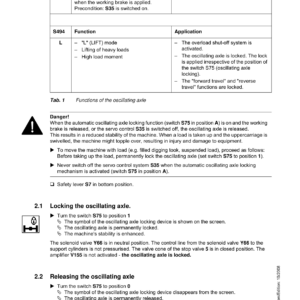
- 14 Oscillating axle support
- 14.10 Oscillating axle support with automatic control
- 14.20 Support cylinder
- 15 Brake system / Air pressure system
- 15.05 Operating pressures of the brake system
- 15.10 Hydraulic brake system
- 15.20 Compact brake block
- 15.51 Compressed air – wagon brake system
- 16 Special equipment / Accessory kits
- 16.01 Pipe fracture safety valve for hoist cylinder
- 16.02 Pipe fracture safety valve for stick cylinder
- 16.03 Pipe fracture safety valve for boom cylinders
- 16.10 Optional equipment control
- 16.11 Terminal assignment of attachments
- 16.12 Changeover bucket – closing cylinder
- 16.13 LIEBHERR hydro magnet
- 16.14 Camera monitoring system
- 16.15 Hydraulic quick-change adapter
- 16.18 LIKUFIX hydraulic coupling system
- 16.19 Hydraulic-electric LIKUFIX coupling system
- 16.21 Pressure and flow reduction
- 16.22 Hydraulic hammer
- 16.24 Swivel rotator TR-20/TR-25
- 16.40 Accessory kit AS1
- 16.50 Stroke and boom limitation
- 16.52 Adjustment of the stroke and boom limitation parameters
- 16.54 Inclination sensor
- 16.55 Changeover position pressure control
- 16.56 Switching between position and pressure control
- 16.57 Emergency hydraulics
- 16.60 Refuelling pump
- 16.62 Individual control
- 16.65 Bypass filter
- 16.69 LIEBHERR bypass filter
- 16.75 3rd axle for road travel
- 17 Operator's cab / Heating and air-conditioning
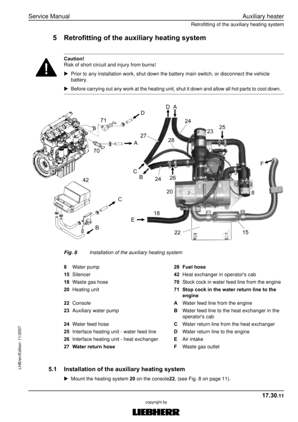
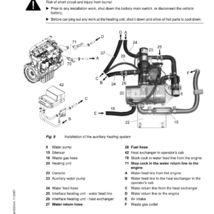
- 17.30 Auxiliary heater
- 17.40 Inspection and repair instructions for heating and air-conditioning system
- 17.50 Heating and air-conditioning system
- 18 Rail roader installations / Attachments
- 18.50 Repair instructions for lubrication hoses
- 18.51 Central lubrication system
- 170.015 Semi-automatic central lubrication system
- 18.54 Fully automatic central lubricating system
- 18.56 Central lubrication pump
- 18.58 SX-E progressive distributor
- 18.59 MX-F progressive distributor
- 19 Tank arrangement
Additional information
| PIN Type | Type 729 & 730 & 931, Type 1030 & 1031 & 1032, Type 1033, Type 1384, Type 1385 |
|---|---|
| Manual | Service Repair Manual, Operators Manual |
Be the first to review “Liebherr A900 C ZW, A900 C ZW EDC Litronic Excavator Operators Service Repair Manual”
You must be logged in to post a review.
Reviews
There are no reviews yet.