
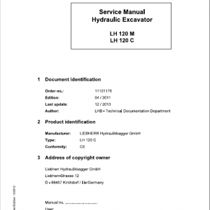
Liebherr A900 B Litronic Excavator Operators Service Repair Manual
$39.00
Manual Included:
- Service Repair Manual: 1902 pages
- Operators Manual: 176 pages
Specifications:
- Type: Excavator
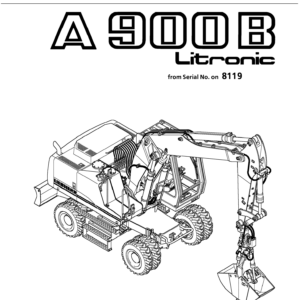
- Model: A900 B
- PIN/Type: 662
- Manuals: Operators Manual, Repair Manual
- Publication Numbers: 8720003, 8717911
- Language: English
- Format: PDF
- Description
- Reviews (0)
Description
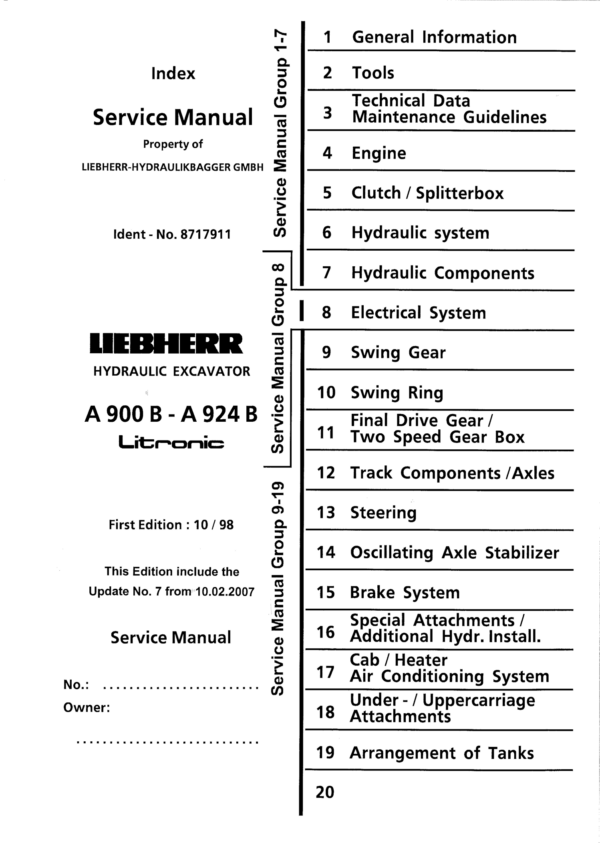
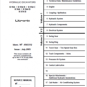
Table of Content – Liebherr A900 B Type 662
- Index
-
- Index Group 1 – 7
- Index Group 8
- Index Group 9 – 19
-
- 1. General Information
- 1.02 Data – Introduction of changes
- 1.10 Safety guidelines
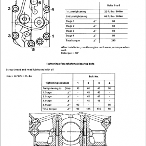
- 1.20 Tightening torques for screws and pins
- 1.21 Tightening torques for pins
- 1.22 Assembly information for piston and piston nut (Factory standard 4121)
- 1.24 Assembly information for piston rod bearing (Factory standard 4122)
- 1.50 Service fluids
- 1.55 Lubrication chart ML05
- 1.56 Lubrication chart ML07
- 2. Tools
- 2.01 Special Tools for Excavator
- 2.02 Special Tools for Diesel Engine D 924
- 2.03 Special Tools for Diesel Engine BF 1013
- 2.05 Special Tools for Hydraulic
- 2.06 Special Tools for Electrical Connections
- 2.07 Special Tools for Gears
- 2.08 Special Tools for Axles
- 2.12 Piston wrench for hydraulic cylinder
- 2.13 Pulling device for piston rod bearing of the rams
- 2.14 Slotted nut wrench for swing gear
- 2.15 Release mechanism for swing gear
- 3. Technical Data Maintenance Guidelines
- 3.11 Technical Data A 900 B Litronic / from 6001
- 3.21 Maintenance Guidelines A 900 B Litronic / from 6001
- 4. Engine
- 4.05 Technical data Diesel engine BF 4 M 1013 E
- 4.10 Technical data Diesel engine D 924 T – E
- 4.11 Technical data Diesel engine D 924 TI -EA2
- 5. Clutch / Splitterbox
- 5.10 Coupling A 900 B Litronic / from 6001 A 904 Litronic / from 6001 A 914 Litronic / from 6001 A 914 B Litronic / from 15993 A 924 Litronic / from 6001 A 924 B Litronic / from 15993
- 6. Hydraulic System
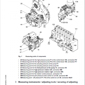
- 6.01 Hydraulic System
- 6.11.01 Adjustment procedure A 900 B Litronic /from 6001
- 6.16 Hydraulic system with LUDV System A 900 B Litronic / A 904 Litronic /from 6001
- 6.31.01 Hydraulic system A 900 B Litronic /from 6001
- 6.31.11 Hydraulic system A 900 B Litronic /from 6378
- 6.31.21 Hydraulic system A 900 B Litronic /from 6707
- 6.01 Hydraulic System
- 7. Hydraulic Components
- 7.01 Hydraulic Components to 7.42
- 7.01 Hydraulic pumps Removal and installation A 900 B – 924 B Litronic / A 904 Industry / from 6001
- 7.02 Pump component LPV Technical Data A 900 B – 904 Litronic / from 6001
- 7.04 Pump component LPV Design and function A 900 B – 904 Litronic / from 6001
- 7.20 Hydraulic motors / types A 900 B – A 924 B Litronic / from 6001
- 7.21 Hydraulic fixed displacement motor FMF A 900 B Litronic / A 904 Litronic / A 904 Industry / from 6001
- 7.26 Hydraulic variable display motor LMV A 900 B – A 924 B Litronic / A 904 Industry /from 6001
- 7.30 Hydraulic cylinder (Design, function, sealing) A 900 B – A 924 B Litronic / A 904 Industry /from 6001
- 7.31 Hydraulic cylinder (Times to extend and retract) A 900 B – A 924 B Litronic / from 6001 A 904 Industry / from 6001
- 7.34 Hydraulic cylinder (Types) A 900 B Litronic /from 6001
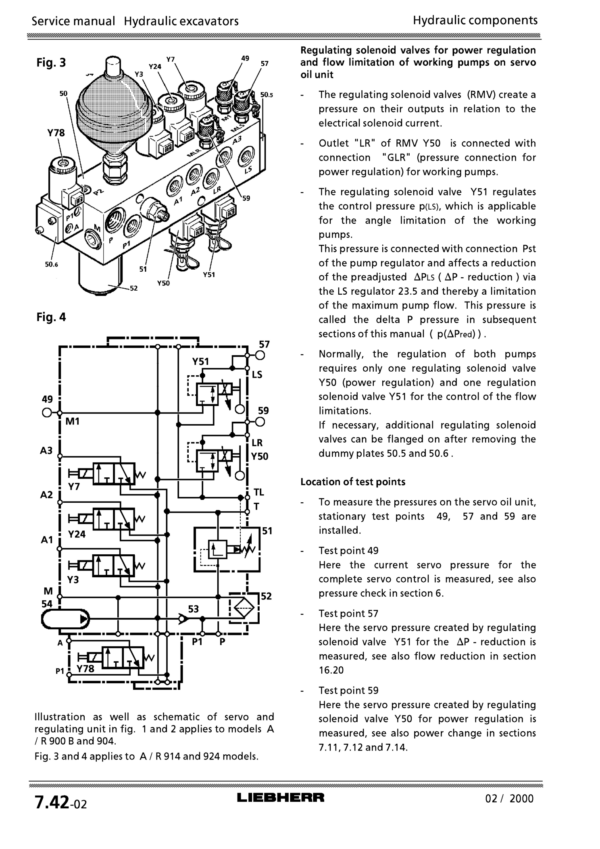
- 7.42 Regulating and servo oil unit A 900 B – A 924 B Litronic /from 6001
- 7.45 Servo Control Valve 4 way A 900 B – A 924 B Litronic / A 904 Industry /from 6001
- 7.02 Hydraulic Components from 7.45
- 7.47 Servo Control Valve 2 way (Design and Function) A 900 B – A 924 B Litronic / A 904 Industry /from 6001
- 7.48 Servo Control Valve 2 way (Design and Function) A 900 B – A 924 B Litronic /A 904 Industy / from 6001
- 7.49 Servo Control Valve 1 way (Design and Function) A 900 B – A 924 B Litronic / A 904 Industry /from 6001
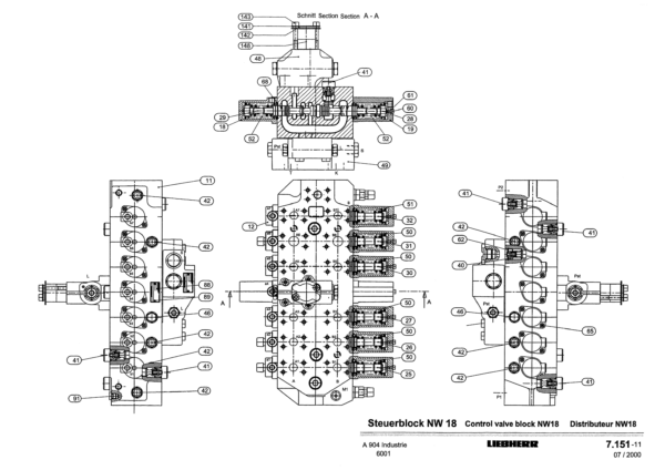
- 7.51 Control valve A 900 B Litronic / A 904 Litronic /from 6001
- 7.64 Leak oil check directional valve A 900 B – A 924 B Litronic / from 6001
- 7.76 Rotary connection 6 – way A 900 B – A 924 B Litronic / from 6001
- 7.78 Rotary connection 7 – way A 900 B – A 924 B Litronic / from 6001
- 7.80 TC – Valve A 900 B – A 904 Litronic / from 6001
- 7.86 Dual load holding valve A 900 B – A 904 Litronic / from 6001
- 7.90 Restrictor check valve A 900 B – 924 B Litronic / from 6001
- 7.92 Pressure relief valve A 900 B – 924 B Litronic / from 6001
- 7.01 Hydraulic Components to 7.42
- 8. Electrical System
- 8.10 Electrical system A 900 B Li – A 924 B Li / from 6001
- 8.31.01 Electrical system A 900 B Litronic / from 6001
- 8.31.31 Electrical system A 900 B Litronic / from 6618
- 8.45 Electrical system A 900 B Li – A 924 B Li / from 6001
- 8.71 Monitoring Display A 900 B Li – A 924 B Li / from 6001
- 8.74 Switch panel A 900 B Li – A 924 B Li / from 6001
- 9. Swing Gear
- 9.10 Swing Gear A 900 B Litronic / from 6001 A 904 Litronic / from 6001 A 914 Litronic / from 6001 A 924 Litronic / from 6001
- 9.20 Swing Brake A 900 B Litronic / from 6001 A 900 C Litronic / from 14675 A 904 Litronic / from 6001 A 914 Litronic / from 6001 A 924 Litronic / from 6001
- 10. Swing Ring
- 10.10 Swing Ring
- 11. Final Drive Gear / Two Speed Gear Box
- 11.10 Distributor gear 2 HL 100
- 11.30 Gear control HBGV – Block for 2 HL 100
- 12. Track Components / Axles
- 12.10 Steering axle APL – B 755 A 900 B Litronic / from 6001
- 12.20 Fixed axle AP – B 755 A 900 B Litronic / from 6001
- 12.22 Fixed axle AP – B 755 A 900 B Litronic / from 6001
- 12.40 Differential A 900 B Litronic / from 6001
- 13. Steering
- 13.10 Hydrostatic Steering A 900 B Litronic / A 904 Litronic / A 914 Litronic / A 924 Litronic /from 6001
- 13.20 Servostat A 900 B Litronic / A 904 Litronic / A 914 Litronic / A 924 Litronic /from 6001
- 13.30 Steering Cylinder A 900 B Litronic /from 6001
- 13.40 Flow Indicator A 900 B Litronic / A 904 Litronic / A 914 Litronic / A 924 Litronic /from 6001
- 14. Oscillating Axle Stabilizer
- 14.10 Oscillating axle stabilizer
- 14.20 Stabilizing cylinder
- 15. Brake System
- 15.05 General Data and Operating Pressures
- 15.10 Hydraulic Brake System
- 15.20 Compact Brake Block
- 16. Special Attachments / Additional Hydraulic Install.
- 16.01 Special Attachments / Additional Hydr.Install.
- 16.02 Load check valve A 900 B – A 904 Litronic / from 6001
- 16.06 Overload warning device A 900 B – A 904 Litronic / from 6001
- 16.12 Lift stop A 900 B – A 924 B Litronic / from 6001
- 16.14 Quick change adapter A 900 B – A 924 Litronic / from 6001
- 16.15 Quick change adapter A 900 B – A 924 B Litronic / from 05.2002
- 16.18 Hydraulic coupling LIKUFIX A 900 B – A 924 B Litronic / from 6001
- 16.20 Flow reduction A 900 B – A 924 Litronic / from 6001
- 16.22 Hydraulic hammer A 900 B – A 924 B Litronic / from 6001
- 16.30 Installation kit Speeder A 900 B – A 924 B Litronic / from 6001
- 16.32 Installation kit A 900 B – A 924 Litronic / from 6001
- 16.33 Installation kit A 914 B – A 924 B Litronic / from 15993
- 16.02 Special Attachments / Additional Hydr.Install.
- 16.40 Special installation kit AS 1 A 900 B – A 904 Litronic / from 6001
- 16.45 Special installation kit AHS 11 A 900 B – A 904 Litronic / from 6001
- 16.48 Special installation kit AHS 12 A 900 B – A 904 Litronic / from 6001
- 16.62 Individual control A 900 B – A 924 B Litronic / from 6001
- 16.68 Filling device A 900 B – A 924 B Litronic / from 6001
- 16.01 Special Attachments / Additional Hydr.Install.
- 17. Cab / Heater Air Conditioning System
- 17.30 Additional Heater D5 WS
- 17.50 Air Conditioning System “KONVEKTA”
- 17.61 Regulation solenoid valve for cab heater A 904 – A 924 B Litronic
- 18. Under / -Uppercarriage Attachments
- 18.10 Combinations A 900 B Litronic / from 6001
Be the first to review “Liebherr A900 B Litronic Excavator Operators Service Repair Manual”
You must be logged in to post a review.
Reviews
There are no reviews yet.