


Liebherr A311 Litronic Excavator Operators Service Repair Manual
Price range: $40.00 through $45.00
Manual Included:
PIN/Type – 718
- Service Repair Manual: 2661 pages
- Operators Manual: 217 pages
PIN/Type – 1036
- Service Repair Manual: 3323 pages
- Operators Manual: 258 pages
Specifications:
- Type: Excavator
- Model: A311
- PIN/Type: 718 & 1036
- Manuals: Operators Manual, Repair Manual
- Language: English
- Format: PDF
- Description
- Additional information
- Reviews (0)
Description
Table of Content – Liebherr Service Repair Manual – A 311
- Book I Chapter 1-7 (Page 1)
- Identification (Page 1)
- Introduction (Page 3)
- Main group directory (Page 5)
- Book II Chapter 8 (Page -1)
- Identification (Page 7)
- Main group directory (Page 9)
- Book III Chapter 9-19 (Page -1)
- Identification (Page 11)
- Main group directory (Page 13)
- 1. General Information (Page 32)
- 1.02 Modification of series (Page 17)
- 1.10 Safety instructions (Page 19)
- 1.20 Tightening torques (WN 4037 I) (Page 33)
- 1.21 Tightening torquex for screw connections (Page 39)
- 1.22 Assembly instruction for hydraulic cylinder (WN 4121B) (Page 43)
- 1.24 Assembly instruction for hydraulic cylinder (WN 4122B) (Page 49)
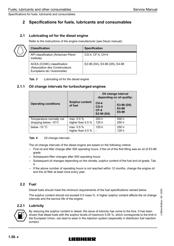
- 1.50 Fuels and lubricants (Page 53)
- 1.55 Lubricant list TE-ML 05 (Page 65)
- 1.56 Lubricant list TE-ML 07 (Page 77)
- 2. Tools (Page 89)
- 2.01 Special tools general (Page 91)
- 2.03 Special tools for diesel engines (Page 99)
- 2.05 Special tools for hydraulic systems (Page 105)
- 2.06 Special tools for electric systems (Page 109)
- 2.07 Special tools for gears (Page 113)
- 2.08 Special tools for axles (Page 115)
- 2.12 Assembly tools for hydraulic cylinders (Page 119)
- 2.13 Mounting device for piston rod bearings (Page 127)
- 2.14 Slotted nut wrench for slewing gear (Page 129)
- 2.15 Mounting device for slewing gear (Page 131)
- 2.16 Mounting device for travel gear (Page 133)
- 3. Technical data/maintenance instructions (Page 135)
- 3.11 Technical data (Page 141)
- 3.32 Inspection and maintenance schedule (Page 171)
- 4. Drive motor (Page 183)
- 5. Coupling/pump distribution gear (Page 199)
- 6. Hydraulic system (Page 211)
- 6.11 Adjustment protocol A 311 Li 20222-27111 (Page 233)
- 6.11.11 Adjustment protocol A 311 Li 27112- (Page 243)
- 6.22 Layout of hydraulic system A 309 Li – A 311 Li (Page 307)
- 6.30 Adjustment guidelines for hydraulic system A 3109 Li – A 311 Li (Page 341)
- 6.40 Hydraulic system A 309 Li 20221-23502 / A 311 Li 20222-23506 (Page 401)
- 6.40.11 Hydraulic system A 309 Li 23503-27109 / A 311 Li 23507-27111 (Page 411)
- 6.40.21 Hydraulic system A 309 Li 27110- / A 311 Li 27112- (Page 421)
- 7. Hydraulic components (Page 519)
- 7.01 Hydraulic pumps – dismantling, installation and initial operation (Page 523)
- 7.02 Double variable-displacement pump A8VO (Page 527)
- 7.05 LPV variable displacement pump (Page 543)
- 7.20 Cooling unit (Page 591)
- 7.24.1 FMF hydraulic fixed displacement motor (Page 601)
- 7.24.11 FMF hydraulic fixed displacement motor (Page 609)
- 7.26 LMV regulating motor (Page 617)
- 7.27 DMVA regulating motor (Page 633)
- 7.28 Regulating motor A6VE (Page 649)
- 7.30 Hydraulic cylinder (Page 667)
- 7.40 Control oil and regulation unit A 309 Li – A 311 Li (Page 691)
- 7.45 Pilot control unit 4 x (Page 703)
- 7.46.1 Pilot control unit 2 way for travel gear drive (Page 711)
- 7.46.11 Pilot control unit 4 way for travel gear drive (Page 719)
- 7.47 Pilot control valve 2 x for installation kir (Page 725)
- 7.48 Pilot control valve 2 x for support (Page 731)
- 7.49 Pilot control valve 1 x (Page 737)
- 7.75 Rotary connection 1 x (Page 837)
- 7.76 Rotary connection 6 x (Page 843)
- 7.77 Rotary connection 5 x (Page 851)
- 7.78 Rotary connection 7 x (Page 857)
- 7.80 TC valve (Page 863)
- 8. Electrical System (Page 867)
- 8.09 Component arrangement A 309 LI 20221- / A 311 LI 20222- (Page 869)
- 8.20 Electrical system A 309 Li 20221 / A 311 Li 20222- (Page 923)
- 8.22 Electrical system A 309 Li 29269 / A 311 Li 29270 (Page 977)
- 9. Slewing gear mechanism (Page 1665)
- 10. Slewing ring (Page 1695)
- 11. Transmission (Page 1705)
- 12. Axles (Page 1851)
- 13. Steering (Page 2149)
- 14. Oscillating axle support (Page 2233)
- 15. Brake system (Page 2257)
- 16. Special equipment/accessory kits (Page 2283)
- 17. Cab Heater / Air Conditioning System (Page 2607)
- 18. Undercarriage / uppercarriage / attachments (Page 2637)
- 19. Arrangement of Tanks (Page 2644)
- 19.10 Tank arrangement (Page 2646)
Additional information
| PIN/Type | 718, 1036 |
|---|
Be the first to review “Liebherr A311 Litronic Excavator Operators Service Repair Manual”
You must be logged in to post a review.
Reviews
There are no reviews yet.