
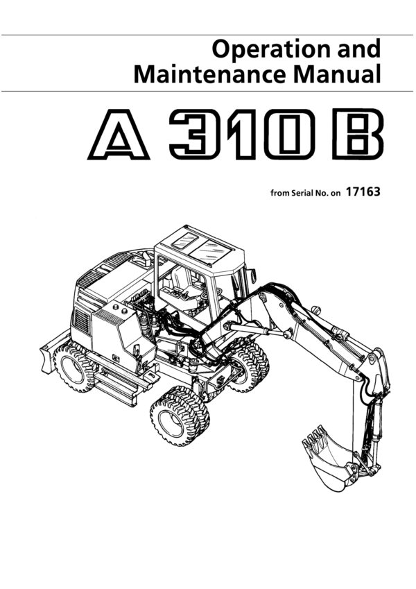
Liebherr A310B Hydraulic Excavator Operators Service Repair Manual
$40.00
Manual Included:
- Service Repair Manual: 2010 pages
- Operators Manual: 149 pages
Specifications:
- Type: Excavator
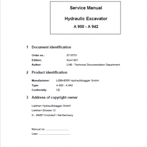
- Model: A310B
- PIN/Type: All
- Manuals: Operators Manual, Repair Manual
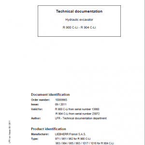
- Publication Numbers: 8720233, 8717522
- Language: English
- Format: PDF
- Description
- Reviews (0)
Description
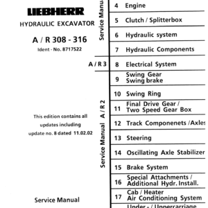
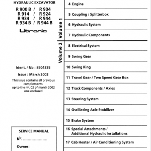
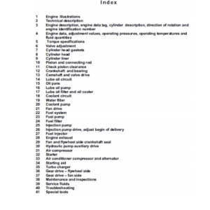
Table of Content – Liebherr Service Repair Manual – A 310B
- Book I group 1-7 (Page -1)
- Index (Page 1)
- Foreword (Page 3)
- Page index 1-7 (Page 5)
- Book II Group 8 (Page 17)
- Index (Page 17)
- Page Index 8 (Page 19)
- Book III group 9-19 (Page 27)
- Index (Page 27)
- Page Index 9-19 (Page 29)
- 1. General Information (Page 43)
- 1.10 Safety Guidelines (Page 45)
- 1.20 Charts / Norms (Page 55)
- 1.50 Service Fluids (Page 69)
- 1.55 Oil Specification Chart “LS-Oil” (Page 79)
- Tools (Page 85)
- 2.01 Listing of special tools for excavators (general) (Page 87)
- 2.03 Listing of special tools for Deutz Engine (Page 99)
- 2.05 Listing of special tools for hydraulic system (Page 119)
- 2.06 Listing of special tools for electrical connectors (Page 135)
- 2.07 Listing of special tools for gears (Page 145)
- 2.08 Listing of special tools for axles (Page 151)
- 2.10 Listing of special tools for Piston Wrech (Page 161)
- 2.11 Listing of special tools for Special assy spanner (Page 163)
- 2.12 Listing of special tools for Removal device (Page 165)
- 2.13 Listing of special tools for Ring nut spanner (Page 171)
- 2.14 Listing of special tools for Spool travel measuring tool (Page 173)
- 2.15 Listing of special tools for Testing device (Page 175)
- 2.16 Listing of special tools for Push out and centering pin (Page 177)
- 2.17 Listing of special tools for Intermiate plate (Page 179)
- 3. Technical Data / Maintenance Guidelines (Page 181)
- 3.10 Technical Data A 310 from 101 (Page 187)
- 3.11 Technical Data A 310 B from 1001 (Page 189)
- 3.20 Maintenance Guidelines A 310 from 101 (Page 209)
- 3.21 Maintenance Guidelines A 310 B from 1001 (Page 211)
- 4. Engine (Page 223)
- 5. Clutch / Splitterbox (Page 245)
- 6. Hydraulic system (Page 255)
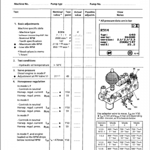
- 6.10 Hydraulic System Pressure Settings and Flow A 310 from 101 / A 310 B from 1001 (Page 261)
- 6.20 Hydraulic System – High and Low Pressure Circuit A 310 B from 1001 (Page 299)
- 6.30 Hydraulic System – High Pressure Circuit A 310 from 101 (Page 315)
- 6.35 Hydraulic System – Low Pressure Circuit A 310 from 101 (Page 319)
- 7. Hydraulic Components (Page 355)
- 7.12 Variable Displacement Pumps A 10 V “DFSR/DSLR” A 310 from 101 (Page 369)
- 7.84 Suction Valve A 310 from 101 (Page 631)
- 7.86 Pressure Relief Valve, direct controlled A 310 from 101 (Page 635)
- 7.90 Distributor Valve A 310 from 101 (Page 639)
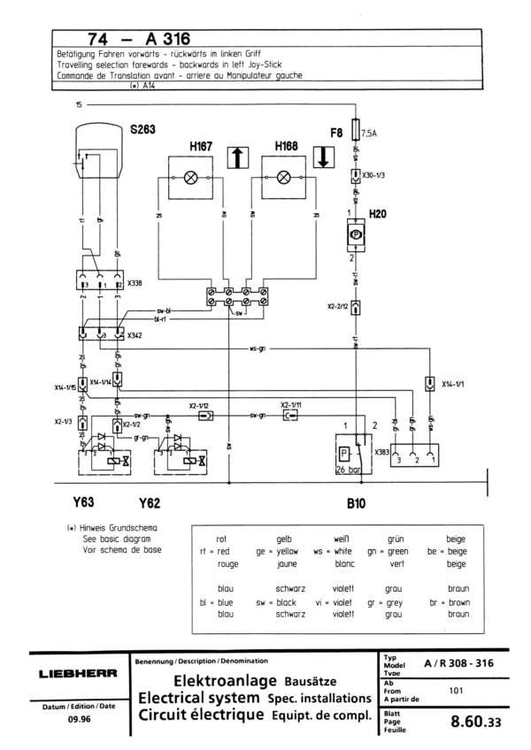
- 8. Electrical System (Page 663)
- 8.10 Components of the Electric system A 310 / from 101 (Page 683)
- 8.11.01 Components of the Electric system A 310 B / from 1001 (Page 693)
- 8.11.10 Components of the Electric system A 310 B / from 1298 (Page 701)
- 8.40 Electric System Basic Machine A 310 / from 101 (Page 835)
- 8.42 Electric System Basic Machine A 310 B / from 1001 (Page 843)
- 8.43 Electric System Basic Machine A 310 / from 1298 (Page 853)
- 9. Swing Gear / Swing Brake (Page 1133)
- 10. Swing Ring (Page 1173)
- 11. Travel Gear / Transmission (Page 1183)
- 11.30 Transmission Hurth 353 1-gear A 310 from 101 (Page 1231)
- 11.32 Transmission Hurth 355 2-gear A 310 B from 1001 (Page 1239)
- 12. Track Components / Axles (Page 1361)
- 13. Steering (Page 1553)
- 14. Oscillating Axle Stabilizer (Page 1661)
- 14.10 Oscillating Axle Stabilizer A 310 from 101 (Page 1663)
- 14.20 Stabilizer Cylinder A 310 from 101 (Page 1675)
- 15. Brake System (Page 1687)
- 15.05 General Data and Operating Pressures A 310 from 101 (Page 1689)
- 15.20 Brake system / Parking Brake A 310 from 101 (Page 1705)
- 16. Special Attachments / Additional Hydraulic Installation (Page 1715)
- 16.55 Attachment Installation Kit Speeder A 310 from 101 (Page 1897)
- 17. Cab / Heater / Air Conditioning System (Page 1969)
- 18. Under- / Uppercarriage / Attachments (Page 1987)
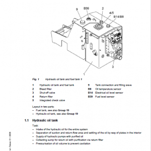
- 19. Arrangement of Tanks (Page 1999)
Be the first to review “Liebherr A310B Hydraulic Excavator Operators Service Repair Manual”
You must be logged in to post a review.
Reviews
There are no reviews yet.