
Liebherr A308 Hydraulic Excavator Operators Service Repair Manual
$40.00
Manual Included:
- Service Repair Manual: 2010 pages
- Operators Manual: 147 pages
Specifications:
- Type: Excavator
- Model: A308
- PIN/Type: All
- Manuals: Operators Manual, Repair Manual
- Publication Numbers: 8720232, 8717522
- Language: English
- Format: PDF
- Description
- Reviews (0)
Description
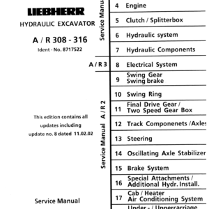
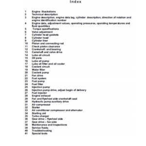
Table of Content – Service Repair Manual (A 308)
- Book I group 1- 7 (Page -1)
- Index (Page 1)
- Foreword (Page 3)
- Page index 1-7 (Page 5)
- Book II Group 8 (Page 17)
- Index (Page 17)
- Page Index 8 (Page 19)
- Book III group 9-19 (Page 27)
- Index (Page 27)
- Page Index 9-19 (Page 29)
- General Information (Page 43)
- 1.10 Safety Guidelines (Page 45)
- 1.20 Charts / Norms (Page 55)
- 1.50 Service Fluids (Page 69)
- 1.55 Oil Specification Chart “LS-Oil” (Page 79)
- Tools (Page 85)
- 2.01 Listing of special tools for excavators (general) (Page 87)
- 2.03 Listing of special tools for Deutz Engine (Page 99)
- 2.05 Listing of special tools for hydraulic system (Page 119)
- 2.06 Listing of special tools for electrical connectors (Page 135)
- 2.07 Listing of special tools for gears (Page 145)
- 2.08 Listing of special tools for axles (Page 151)
- 2.10 Listing of special tools for Piston Wrech (Page 161)
- 2.11 Listing of special tools for Special assy spanner (Page 163)
- 2.12 Listing of special tools for Removal device (Page 165)
- 2.13 Listing of special tools for Ring nut spanner (Page 171)
- 2.14 Listing of special tools for Spool travel measuring tool (Page 173)
- 2.15 Listing of special tools for Testing device (Page 175)
- 2.16 Listing of special tools for Push out and centering pin (Page 177)
- 2.17 Listing of special tools for Intermiate plate (Page 179)
- Technical Data / Maintenance Guidelines (Page 181)
- 3.08 Technical Data A 308 from 101 (Page 183)
- 3.18 Maintenance Guidelines A 308 from 101 (Page 205)
- Engine (Page 223)
- 4.08 Engine BF 4 M 1011 F A 308 from 101 (Page 225)
- 4.09 Engine BF 4 M 2011 A 308 from 12009 (Page 229)
- Clutch / Splitterbox (Page 245)
- 5.05 Elastic Coupling A 308 (Page 247)
- Hydraulic system (Page 255)
- 6.08 Hydraulic System Pressure Settings and Flow A 308 from 101 (Page 257)
- 6.14 Adjustment Procedure A 308 from 101 (Page 275)
- 6.20 Hydraulic System – High and Low Pressure Circuit A 308 from 101 (Page 299)
- Hydraulic Components (Page 355)
- 7.14 Variable Displacement Pumps A 10 V “DFSR/DFSR” A 308 from 101 (Page 385)
- 7.16 Pump Flow Diaqgramm A 308 from 101 (Page 415)
- 7.22 Hydraulic Fixed Displacement Motor A 2 FE Travel- and Slewing Gear A 308 from 101 (Page 429)
- 7.26.01 Hydraulic Variable Displacement Motor A 6 VM HA A 308 from 101 (Page 437)
- 7.26.11 Hydraulic Variable Displacement Motor A 6 VM HA A 308 from 271 (Page 449)
- 7.30 Hydraulic Cylinder A 308 from 101 (Page 493)
- 7.35 Hydraulic Cylinder Chart A 308 from 101 (Page 505)
- 7.43 Hydraulic Servo Control A 308 from 101 (Page 519)
- 7.46 Control Oil Unit A 308 from 101 (Page 523)
- 7.50 Servo Control with Joystick Lever A 308 from 101 (Page 527)
- 7.54 Servo Control with Foot Pedal 2-way (for attachment installation) A 308 from 101 (Page 541)
- 7.55 Servo Control with Foot Pedal 1-way (for travel gear) A 308 from 101 (Page 545)
- 7.66 Control Valve Block 8-way NG 16 Rexroth A 308 from 101 (Page 569)
- 7.71 Rotary connection 1-way Tries A 308 from 101 (Page 601)
- 7.72 Rotary connection 6-way Tries A 308 from 101 (Page 605)
- 7.74 Rotary connection 5- and 7 way Liebherr A 308 from 101 (Page 613)
- 7.83 Secondary-PR Valve with Suction Function A 308 from 101 (Page 629)
- 7.85 Suction Valve A 308 from 101 (Page 633)
- 7.88 Restrictor Check Valve A 308 from 101 (Page 637)
- 7.91 Check Valve with hydraul. Release A 308 from 101 (Page 641)
- 7.92 Dual Check Valve with hydraul. Release A 308 from 101 (Page 643)
- 7.94 Travel Brake Valve A 308 from 101 (Page 645)
- 7.96 Load Holding Valve A 308 from 101 (Page 649)
- 7.98 Brake Valves for Swing Motor A 308 from 101 (Page 657)
- Electrical System (Page 663)
- 8.08 Components of the Electric system A 308 from 101 (Page 665)
- 8.09 Components of the Electric system A 308 from 454 (Page 673)
- 8.30 Electric System Basic Machine A 308 from 101 (Page 795)
- 8.31 Electric System Basic Machine A 308 from 454 (Page 807)
- 8.60 Electric System Installations Kits A 308 from 101 (Page 959)
- 8.70 Slip Ring Rotary Connection A 308 from 101 (Page 1129)
- Swing Gear / Swing Brake (Page 1133)
- 9.12 Swing Gear – Trasmital A 308 from 101 (Page 1145)
- 9.18 Swing Brake A 308 from 101 (Page 1165)
- Swing Ring (Page 1173)
- 10.10 Swing Ring A 308 from 101 (Page 1175)
- Track Components / Axles (Page 1361)
- 12.06 Wear of Track Components A 308 from 101 (Page 1369)
- 12.09 Wear Limits of Track Components A 308 from 101 (Page 1373)
- 12.12 Track Components A 308 from 101 (Page 1375)
- 12.15 Slipring Seal A 308 from 101 (Page 1381)
- 12.26 Idler A 308 from 101 (Page 1383)
- 12.31 Tension Unit A 308 from 101 (Page 1387)
- 12.41 Track Roller A 308 from 101 (Page 1391)
- 12.46 Carrier Roller A 308 from 101 (Page 1393)
- 12.58 Steering Axle with Disk Brake A 308 from 101 (Page 1395)
- 12.70 Fixed Axle with Disk Brake A 308 from 101 (Page 1449)
- 12.79 Differantial A 308 from 101 (Page 1501)
- 12.80 Differantial A 308 from 101 (Page 1509)
- 12.90 Tire Chart A 308 from 101 (Page 1551)
- Steering (Page 1553)
- 13.10 Hydrostatic Steering System A 308 from 101 (Page 1555)
- 13.20 Servostat System A 308 from 101 (Page 1561)
- 13.30 Steering Cylinder A 308 from 101 (Page 1571)
- 13.32 Steering Cylinder A 308 from 101 (Page 1577)
- 13.50 Four Wheel Steering (Installation) A 308 from 101 (Page 1593)
- 13.51 Electronic Four Wheel Steering A 308 from 101 (Page 1613)
- 13.52 Four Wheel Steering (Installation) A 308 from 454 (Page 1629)
- 13.53 Electronic Four Wheel Steering A 308 from 454 (Page 1645)
- Oscillating Axle Stabilizer (Page 1661)
- 14.12 Oscillating Axle Stabilizer A 308 from 101 (Page 1669)
- 14.22 Stabilzer Cylinder A 308 from 101 (Page 1681)
- Brake System (Page 1687)
- 15.06 General Data and Operating Pressures A 308 from 101 (Page 1691)
- 15.10 Hydraulic Brake System / Operating Brake A 308 from 101 (Page 1693)
- 15.30 Compact Brake Block A 308 from 101 (Page 1709)
- Special Attachments / Additional Hydraulic Installation (Page 1715)
- 16.03 Overload Warning Device A 308 from 101 (Page 1717)
- 16.10 Load Holding Valve A 308 from 101 (Page 1739)
- 16.18 Attachment Installation Kit AS1 A 308 from 101 (Page 1769)
- 16.26 Attachment Installation Kit ASH A 308 from 101 (Page 1809)
- 16.35 Attachment Installation Kit AHS 11 A 308 from 101 (Page 1839)
- 16.42 Attachment Installation Kit AHS 3 A 308 from 101 (Page 1859)
- 16.45 Attachment Installation Kit AHS 12 A 308 from 101 (Page 1877)
- 16.59 Attachment Installation Kit Variable Displacement Travel Motor A 308 from 101 (Page 1911)
- 16.80 Quick Change Adapter A 308 from 101 (Page 1929)
- 16.82 Quik Change Adapter A 308 from 03.2002 (Page 1945)
- 16.90 Hydraulic Hammer A 308 from 101 (Page 1957)
- Under- / Uppercarriage / Attachments (Page 1987)
- 18.10 Maintenance free Bearings A 308 from 101 (Page 1989)
- 18.15 Expander Pin A 308 from 101 (Page 1991)
- 18.35 Shut off Installation for Grapple Operation (Page 1997)
Be the first to review “Liebherr A308 Hydraulic Excavator Operators Service Repair Manual”
You must be logged in to post a review.
Reviews
There are no reviews yet.