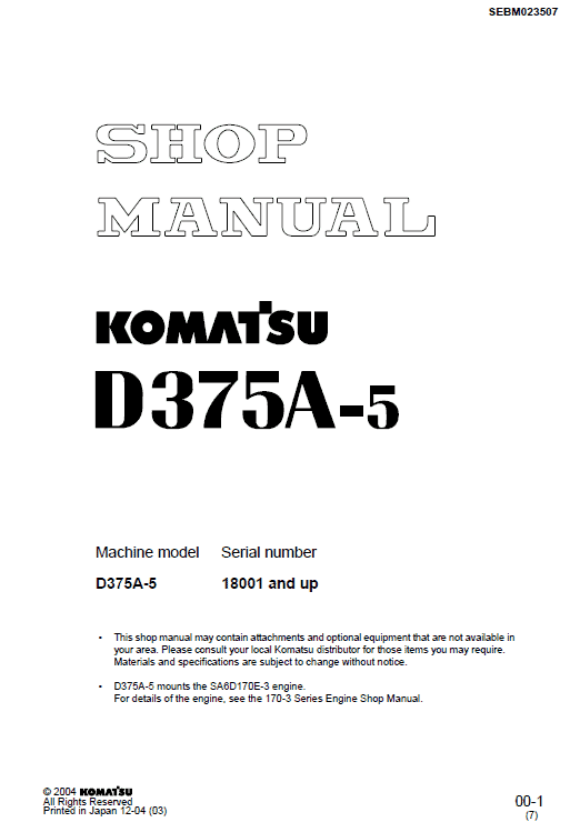
Komatsu D375A-5, D375A-5E0 Dozer Service Manual
$35.00
Manual Included:
- Shop Manual: 1034 pages (D375A-5), 1618 pages (D375A-5E0)
Specifications:
- Brand: Komatsu
- Model: D375A-5, D375A-5E0
- Type: Dozer
- Serial Number:
18200 and up (D375A-5)
50001 and up (D375A-5E0) - Manuals: Shop Manual
- Publication Numbers: SEBM036103 and SEN00986-11
- Language: English
- Format: PDF
- Description
- Reviews (0)
Description
Table of Contents
00 Index and foreword
Foreword and general information
01 Specification
Specification and technical data
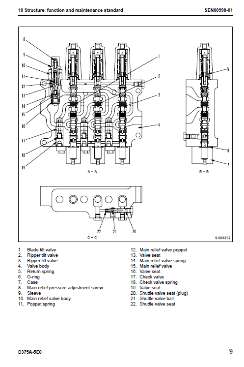
10 Structure, function and maintenance standard
Engine and cooling system
Power train
Undercarriage and frame
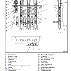
Hydraulic system
Work equipment
Cab and its attachments
Electrical system
20 Standard value table
Standard service value table
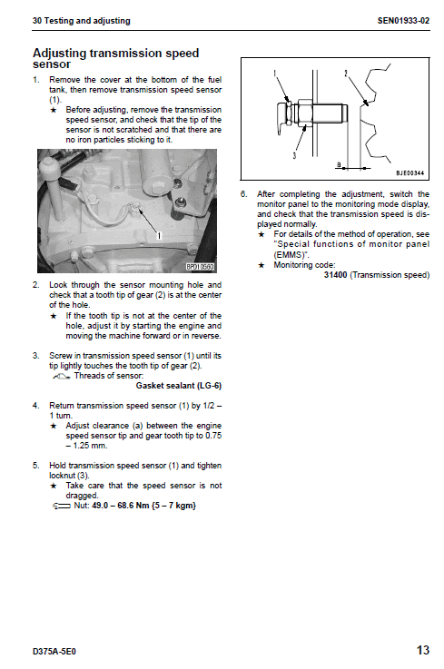
30 Testing and adjusting
40 Troubleshooting
80. Appendix
90 Diagrams and drawings
Composition of shop manual
• This shop manual contains the necessary technical information for services performed in a workshop. For ease of understanding, the manual is divided into the following sections.
00. Index and foreword
01. Specification
• This section explains the specifications of the machine.
10. Structure and function
• This section explains the structure and function of each component. It serves not only to give an understanding for the structure of each component, but also serves as reference material for troubleshooting.
20. Standard value table
• This section explains the standard values for new machine and judgement criteria for testing, adjusting, and troubleshooting. This standard value table is used to check the standard values in testing and adjusting and to judge parts in troubleshooting.
30. Testing and adjusting
This section explains measuring tools and measuring methods for testing and adjusting, as well as the adjusting method of each part. The standard values and judgment criteria for “Testing and adjusting” are explained in “Standard value table”.
40. Troubleshooting
• This section explains how to find out failed parts and how to repair them. The troubleshooting is divided by failure modes. The “S mode” of the troubleshooting related to the engine may be also explained in the Chassis volume and Engine volume. In this case, see the Chassis volume.
50. Disassembly and assembly
• This section explains the special tools and procedures for removing, installing, disassembling, and assembling each component, as well as precautions for them. In addition, tightening torque, and quantity and weight of coating material, oil, grease, and coolant necessary for the work are also explained.
60. Maintenance standard
• This section gives maintenance standard values of each component. The maintenance standard subsection explains the criteria and remedies for disassembly and service.
80. Appendix
• The section contains the equipment which can not be class, field in the other sections.
This section explains the structure, function, testing, adjusting, and troubleshooting for the equipment.
90 Diagrams and drawings
• This section gives hydraulic circuit diagrams and electrical circuit diagrams.
Troubleshooting by failure code, Part 6 SEN01874-00
Failure code [DK30KA] Steering potentiometer 1 disconnection ………………………………………… 4
Failure code [DK30KB] Steering potentiometer 1 short circuit ……………………………………………. 6
Failure code [DK30KX] Steering potentiometer 1 input signal out of range ………………………….. 8
Failure code [DK30KZ] Steering potentiometer 1 disconnection or short circuit ……………………. 9
Failure code [DK30L8] Steering potentiometer 1 analog signal disagreement ……………………… 10
Failure code [DK31KA] Steering potentiometer 2 disconnection ………………………………………… 12
Failure code [DK31KB] Steering potentiometer 2 short circuit ……………………………………………. 14
Failure code [DK40KA] Brake potentiometer disconnection ………………………………………………. 16
Failure code [DK40KB] Brake potentiometer short circuit………………………………………………….. 18
Failure code [DK55KX] Direction potentiometer input signal out of range ……………………………. 20
Failure code [DK55KZ] Direction potentiometer disconnection or short circuit ……………………… 21
Failure code [DK55L8] Direction potentiometer analog signal disagreement ……………………….. 22
Failure code [DK56KA] Direction potentiometer 1 disconnection ……………………………………….. 24
Failure code [DK56KB] Direction potentiometer 1 short circuit …………………………………………… 26
Failure code [DK57KA] Direction potentiometer 2 disconnection ……………………………………….. 28
Failure code [DK57KB] Direction potentiometer 2 short circuit …………………………………………… 30
Failure code [DK60KA] Acceleration sensor disconnection ……………………………………………….. 32
Failure code [DK60KB] Acceleration sensor short circuit…………………………………………………… 34
Failure code [DKH1KA] Pitch angle sensor disconnection ………………………………………………… 36
Failure code [DKH1KB] Pitch angle sensor short circuit ……………………………………………………. 38
Failure code [DKH1KX] Pitch angle sensor input signal out of range ………………………………….. 39
Failure code [DLF1KA] Torque converter output speed sensor disconnection ……………………… 40
Failure code [DLT3KA] Transmission output speed sensor disconnection 1 ………………………… 41
Failure code [dLT3KA] Transmission output speed sensor disconnection 2…………………………. 42
Failure code [DLT3KB] Transmission output speed sensor short circuit………………………………. 43
Failure code [DV00KB] Alarm buzzer short circuit ……………………………………………………………. 44
This is only a few of the failure code
Be the first to review “Komatsu D375A-5, D375A-5E0 Dozer Service Manual”
You must be logged in to post a review.



Reviews
There are no reviews yet.