Komatsu D355-A1 Dozer Service Manual
$29.00
Manual Included:
- Shop Manual: 258 pages
Specifications:
- Brand: Komatsu
- Model: D355-A1
- Type: Dozer
- Serial Numbers: 1010 and up
- Manuals: Shop Manual
- Publication Number: D355A.1-BE3
- Language: English
- Format: PDF
- Description
- Reviews (0)
Description
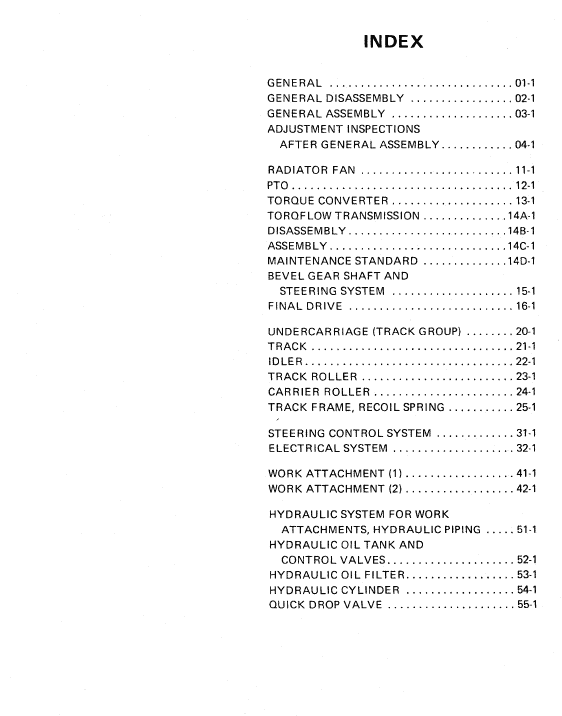
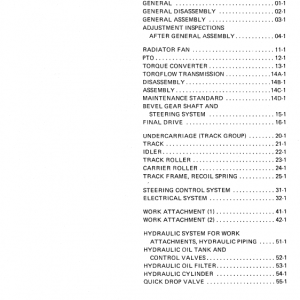
Table of Contents
INDEX
GENERAL . . . . . . . . . . . . . . . . . . . . . . . . . . . . . . 01-1
GENERAL DISASSEMBLY . . . . . . . . . . . . . . . . . 02-1
GENERAL ASSEMBLY . . . . . . . . . . . . . . . . . . . . 03-1
ADJUSTMENT INSPECTIONS AFTER GENERAL ASSEMBLY . . . . . . . . . . . . 04-1
RADIATOR FAN . . . . . . . . . . . . . . . . . . . . . . . . . 11-1
PTO . . . . . . . . . . . . . . . . . . . . . . . . . . . . . . . . . . . . 12-1
TORQUE CONVERTER . . . . . . . . . . . . . . . . . . . . 13-1
TORQFLOW TRANSMISSION . . . . . . . . . . . . . . 14A,1
DISASSEMBLY . . . . . . . . . . . . . . . . . . . . . . . . . . 14B-1
ASSEMBLY . . . . . . . . . . . . . . . . . . . . . . . . . . . . . 14C-1
MAINTENANCE STANDARD . . . . . . . . . . . . . . 14D-1
BEVEL GEAR SHAFT AND STEERING SYSTEM . . . . . . . . . . . . . . . . . . . . 15-1
F I NA L DR IVE . . . . . . . . . . . . . . . . . . . . . . . . . . . 16-1
UNDERCARRIAGE (TRACK GROUP) . . . . . . . . 20-1
TRACK . . . . . . . . . . . . . . . . . . . . . . . . . . . . . . . . . 21-1
IDLER . . . . . . . . . . . . . . . . . . . . . . . . . . . . . . . . . . 22-1
TRACK ROLLER . . . . . . . . . . . . . . . . . . . . . . . . . 23-1
CARRIER ROLLER . . . . . . . . . . . . . . . . . . . . . . . 24-1
TRACK FRAME, RECOIL SPRING . . . . . . . . . . . 25-1
STEERING CONTROL SYSTEM . . . . . . . . . . . . . 31-1
ELECTRICAL SYSTEM . . . . . . . . . . . . . . . . . . . . 32-1
WORK ATTACHMENT (1) . . . . . . . . . . . . . . . . . . 41-1
WORK ATTACHMENT (2) . . . . . . . . . . . . . . . . . . 42-1
HYDRAULIC SYSTEM FOR WORK ATTACHMENTS, HYDRAULIC PIPING . . . . . 51-1
HYDRAULIC OIL TANK AND CONTROL VALVES . . . . . . . . . . . . . . . . . . . . . 52-1
HYDRAULIC OIL FILTER . . . . . . . . . . . . . . . . . . 53-1
HYDRAULIC CYLINDER . . . . . . . . . . . . . . . . . . 54-1
QUICK DROP VALVE . . . . . . . . . . . . . . . . . . . . . 55-1
Torque Converter Assembly
TTo remove the torque converter assembly, first remove both the floor plate and the torque converter under guard, and then disconnect all of the following tubes at the torque converter side:
• Tube from the torque converter regulator valve outlet to the oil cooler inlet.
• Tube from the TOROFLOW transmission control valve outlet to the torque converter relief valve inlet.
• Tube from the torque converter relief valve outlet to the TOR OF LOW transmission lubricating oil relief valve inlet.
• Tube from the torque converter case to the bevel gear shaft case.
• Torque converter lubricating oil tube leading from the TOROFLOW transmission case to the torque converter case.
• Tube for torque converter oil pressure gauge.
• Tube for torque converter oil temperature gauge.
After making sure that all tubes described above have been removed from the torque converter, sling with cables hooked to the eyebolts on the torque converter case. Remove the coupling, and unscrew 15 bolts fastening the torque converter case to the flywheel case as well as one stud nut.
Slightly move the torque converter assembly toward the transmission until the gear mesh between the flywheel and the drive case is disengaged, and then set the torque converter down off the tractor.
Be careful to plug the tubes removed from the torque converter so as to prevent entering of dust
Be the first to review “Komatsu D355-A1 Dozer Service Manual”
You must be logged in to post a review.



Reviews
There are no reviews yet.