")
John Deere Electronic Fuel Injection Systems Repair Technical Manual (CTM68)
$52.00
Manual Included:
- Component Technical Manual: 294 Pages
Specifications:
- Brand: John Deere
- Model: Electronic Fuel Injection Systems
- Type: Engines
- Manuals: Component Technical Manual
- Publication Numbers: CTM68
- Language: English
- Format: PDF
- Description
- Reviews (0)
Description
Table of Content
Group 00—Safety . . . . . . . . . . . . . . . . . . . 00-1
Group 02—General Information
About This Manual . . . . . . . . . . . . . . . . . . . 02-1
Engine Controller Serial Number Plate . . . . . . 02-1
Injection Pump Serial Number Plate . . . . . . . 02-2
Glossary of Terms . . . . . . . . . . . . . . . . . . . 02-3
System Power Requirements . . . . . . . . . . . . 02-5
Engine Controller Environmental
Restrictions . . . . . . . . . . . . . . . . . . . . . . 02-5
Electrical Concepts . . . . . . . . . . . . . . . . . . . 02-5
Using a Digital Multimeter . . . . . . . . . . . . . . 02-6
Use of a Diagnostic Reader . . . . . . . . . . . . . 02-8
Group 05—Fuel Injection System Components
Major System Components . . . . . . . . . . . . . 05-1
Engine Controller . . . . . . . . . . . . . . . . . . . . 05-1
Robert Bosch Injection Pump/Actuator
Assembly . . . . . . . . . . . . . . . . . . . . . . . . 05-2
Nippondenso Injection Pump/Actuator
Assembly . . . . . . . . . . . . . . . . . . . . . . . . 05-5
Auxiliary Speed Sensor . . . . . . . . . . . . . . . . 05-7
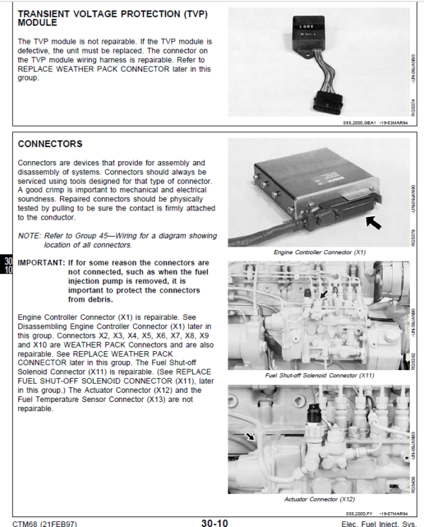
Transient Voltage Protection Module
(TVP) . . . . . . . . . . . . . . . . . . . . . . . . . . 05-8
Group 10—Basic System and Diagnostic Features
How The Electronically-Controlled Fuel Injection System Works
Description . . . . . . . . . . . . . . . . . . . . . . . 10-1
Operation . . . . . . . . . . . . . . . . . . . . . . . 10-2
Self-Diagnosis and Back-Up Features . . . . . . 10-2
Fault Lamp Operation . . . . . . . . . . . . . . . . . 10-3
Governor Modes . . . . . . . . . . . . . . . . . . . . 10-4
Starting Control . . . . . . . . . . . . . . . . . . . . . 10-5
Maximum Fuel Quantity Control . . . . . . . . . . 10-6
Smoke Control . . . . . . . . . . . . . . . . . . . . . 10-7
Fuel Temperature Compensation . . . . . . . . . 10-7
Fuel Flow/Throttle Output Signal . . . . . . . . . . 10-8
Auxiliary Speed Output Signal . . . . . . . . . . . 10-8
Understanding the Throttle Options . . . . . . . . 10-9
Diagnostic Codes Operation . . . . . . . . . . . . 10-11
Using the Electronic Governor
Tester—JT05829 . . . . . . . . . . . . . . . . . . 10-13
Listing of Diagnostic Codes . . . . . . . . . . . . 10-16
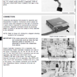
Group 15—Robert Bosch Fuel System Connectors
Engine Controller Connector (X1) . . . . . . . . . 15-1
Auxiliary Speed Sensor Connector (X2) . . . . . 15-4
Fuel Shut-Off Solenoid Connector (X11) . . . . 15-5
Actuator Connector (X12) . . . . . . . . . . . . . . 15-6
Fuel Temperature Sensor Connector
(X13) . . . . . . . . . . . . . . . . . . . . . . . . . . 15-7
In-Line Connectors (X7, X8, X9, X10) . . . . . . 15-7
Service Connectors (X3, X4, X5, X6) . . . . . . . 15-8
Using the Diagnostic Voltages Connector
(X3) . . . . . . . . . . . . . . . . . . . . . . . . . . . 15-8
Using the Diagnostic Reader Connector
(X4) . . . . . . . . . . . . . . . . . . . . . . . . . . 15-12
Group 20—Nippondenso Fuel System Connectors
Engine Controller Connector (X1) . . . . . . . . . 20-1
Auxiliary Speed Sensor Connector (X2) . . . . . 20-4
Fuel Shut-Off Solenoid Connector (X10) . . . . 20-4
Actuator Connectors (X7, X9) . . . . . . . . . . . . 20-5
Fuel Temperature Sensor Connector (X8) . . . . 20-6
Service Connector—X3, X4, X5 . . . . . . . . . . 20-7
Using the Diagnostic Voltages Connector
(X3) . . . . . . . . . . . . . . . . . . . . . . . . . . . 20-7
Using the Diagnostic Reader Connector
(X4) . . . . . . . . . . . . . . . . . . . . . . . . . . 20-11
Group 25—Robert Bosch Fuel Injection System Diagnostic Procedures
How to Start Troubleshooting a Problem . . . . 25-1
Troubleshooting Tools Needed . . . . . . . . . . . 25-2
Troubleshooting Suggestions . . . . . . . . . . . . 25-2
Initial Operational Checks . . . . . . . . . . . . . . 25-6
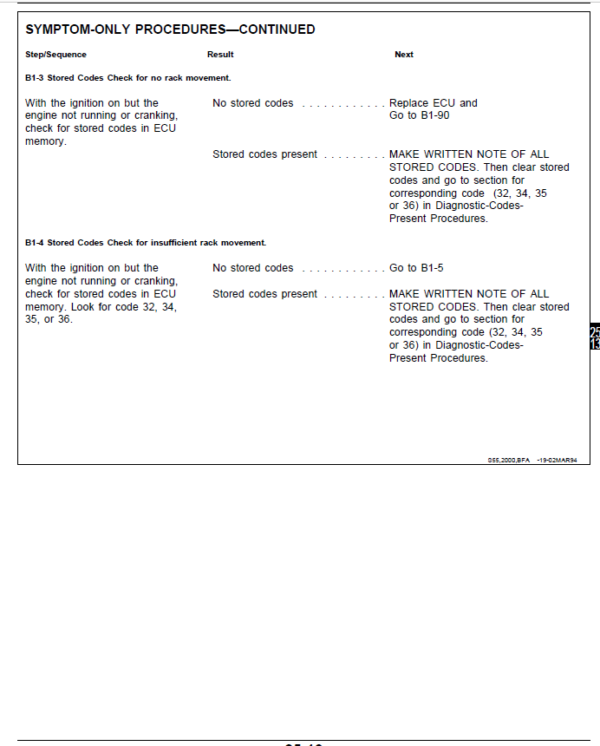
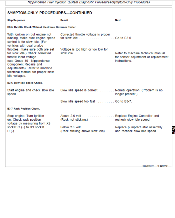
Symptom-Only Procedures . . . . . . . . . . . . 25-11
The three component technical manuals that replace
CTM11 are:
CTM67—This manual covers the 300, 400, 500 and 700 Series OEM engine accessories.
CTM68—This manual covers the electronically controlled fuel injection systems.
CTM77—This manual covers alternators and starting motors.
Information that pertains to both Robert Bosch and Nippondenso electronic fuel injection systems is covered in the following groups:
Group 00—Safety
Group 02—General Information
Group 05—Fuel Injection System Components
Group 10—Basic System and Diagnostic Features
Information which is unique to each system is covered in Groups 15—45. For example, Group 15 contains information on Robert Bosch Fuel System
Connectors. Group 20 contains the same type of information for Nippondenso connectors. All connectors which were previously named “J”
connectors are now referred to as “X” connectors. For instance, J1—Engine Controller Connector is now called X1—Engine Controller Connector
Be the first to review “John Deere Electronic Fuel Injection Systems Repair Technical Manual (CTM68)”
You must be logged in to post a review.
Reviews
There are no reviews yet.