Description
Table of Contents
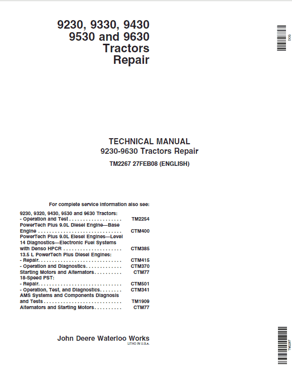
Repair Technical Manual (TM2267)
SECTION 10—General Information
Group 05—Safety
Group 10—General Information
SECTION 20—Engine
Group 00—Component Removal and Installation
Group 05—Engine Repair
SECTION 30—Fuel, Air, and Cooling Systems
Group 05—Diesel Fuel System
Group 10—Air Intake and Exhaust Systems
Group 15—Engine Cooling System
Group 20—Oil Coolers
SECTION 40—Electrical
Group 05—Connectors
Group 10—Wiring Harness Routings
Group 15—Charging Circuit
Group 20—Starting Circuit
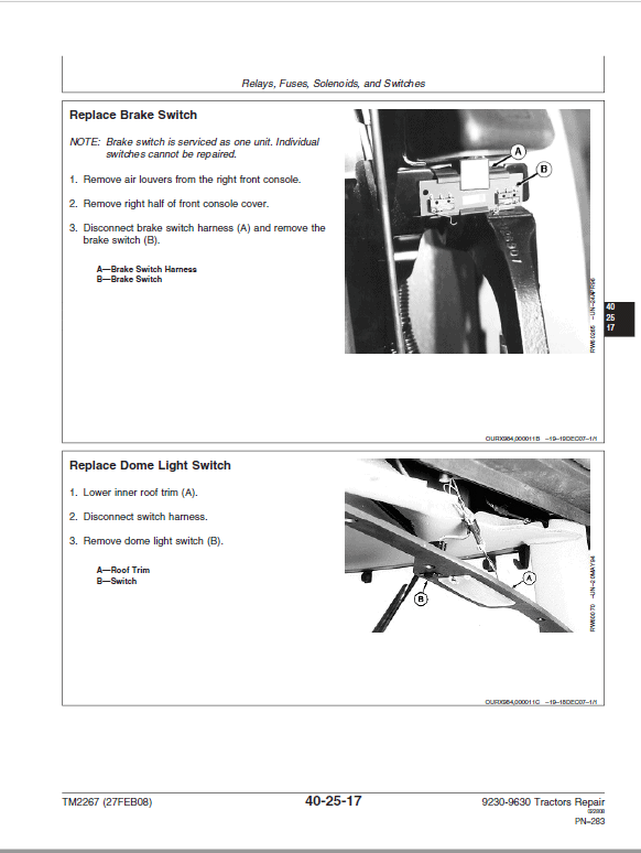
Group 25—Relays, Fuses, Solenoids, and Switches
Group 30—Monitoring Systems and Sensors
Group 35—Armrest Control
Group 40—Implement and Accessory Connectors
Group 45—Convenience and Accessory
Components
SECTION 50—18-Speed Power Shift Transmission
Group 00—Component Removal and Installation
Group 05—In Tractor Repair
Group 10—Transmission Repair
Group 15—Transmission Cleanup
SECTION 55—Mechanical Shift Transmission (MST)
Group 00—Component Removal and Installation
Group 05—Transmission Oil Filter Relief Valve Housing
Group 10—Transmission Control Valve Housing
Group 15—Transmission Pump
Group 20—Transmission Front Cover
Group 25—Hi-Lo Clutch and Brake
Group 30—Hi-Lo Planetary
Group 35—Spacer Housing
Group 40—Traction Clutch
Group 45—Transmission Gear Drives
Group 50—Transmission Cleanup
Group 55—Shift Levers and Linkage
SECTION 56—Drive Systems
Group 00—Component Removal and Installation
Group 05—Engine Coupler
Group 10—Drive Shafts
Group 15—PTO Clutch
Group 20—PTO Clutch Valve
Group 25—PTO Drop Box
SECTION 57—Axles
Group 00—Component Removal and Installation
Group 03—Repair Preparation
Group 05—Input Housing
Group 10—Differential
Group 15—Final Drives
Group 20—Brakes
SECTION 58—Double Reduction Axles
Group 00—Component Removal and Installation
Group 03—Repair Preparation
Group 05—Input Housing
Group 10—Differential
Group 15—Final Drives
Group 20—Brakes
SECTION 60—Steering and Brakes
Group 05—Steering Column
Group 10—Steering Control Valve
Group 15—Steering Cylinders
Group 20—Brakes
Group 40—Secondary Steering (Western European
Tractors)
SECTION 70—Hydraulics
Group 00—Component Removal and Installation
Group 05—Hydraulic System Repair
Group 10—Hydraulic Pump
Group 15—Axle Lubrication Pumps
Group 20—Filter Housings and Control Valves
Group 30—Hitch Valve, Selective Control Valves, and Couplers
Group 35—High-Flow Selective Control Valve— Scraper
Group 40—Hitch
SECTION 80—Miscellaneous
Group 05—Hood and Side Panels
Group 10—Heavy-Duty Wheels
SECTION 90—Operator Station
Group 00—Component Removal and Installation
Group 05—Heating, Ventilating, and Air
Conditioning (HVAC)
Group 10—Air Conditioning System
Group 20—Air Suspension Seat
Group 25—ACTIVE SEAT
Group 30—Armrest
Group 35—Cab Door
SECTION 95—Hinge and Gudgeon
Group 05—Hinge
Group 10—Gudgeon
SECTION 99—Dealer Tools
Group 05—Fabricated Tools
Group 10—Essential and Recommended Tools
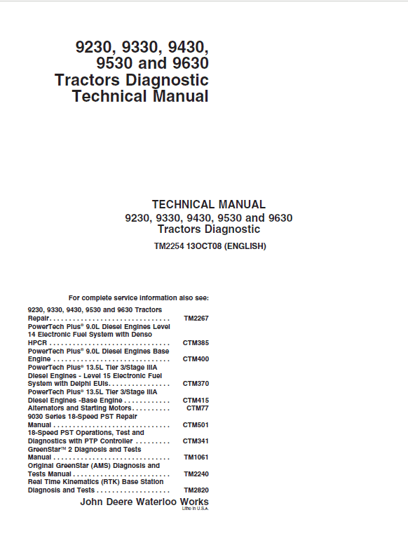
Operator’s Manual (OMAR283034)
SECTION 210—GENERAL
Group 05—Safety
Group 15—General References
SECTION 211—DIAGNOSTIC TROUBLE CODES
Group ACU—ACU Code Diagnostics
Group ASU—ASU Code Diagnostics
Group ATC—ATC Code Diagnostics
Group BRC—BRC Code Diagnostics
Group CAB—CAB Code Diagnostics
Group CCU—CCU Code Diagnostics
Group CLC—CLC Code Diagnostics
Group ECU—ECU Code Diagnostics
Group HCU—HCU Code Diagnostics
Group ICU—ICU Code Diagnostics
Group PTP—PTP Code Diagnostics
Group SCO—SCO Code Diagnostics
Group SCU—SCU Code Diagnostics
Group SSU—SSU Code Diagnostics
Group SUP—SUP Code Diagnostics
Group TEC—TEC Code Diagnostics
Group VLC—VLC Code Diagnostics
SECTION 212—OBSERVABLE SYMPTOMS
Group 20—Engines
Group 30—Fuel and Air
Group 40—Electrical
Group 45—Control Units
Group 50—Power Shift Transmission
Group 55—Manual Shift Transmission
Group 56—Drive Systems
Group 60—Steering and Brakes
Group 70—Hydraulics
Group 90—Operator Station
SECTION 213—SYSTEM DIAGNOSIS
Group 40—Electrical
Group 45—CAN
Group 50—Powershift Transmission
Group 55—Manual Shift Transmission
Group 56—Drive Systems
Group 60—Steering and Brakes
Group 70—Hydraulics
Group 90—Operator Station
SECTION 220—ENGINES
Group 05—Engine Performance
Group 10—Engine Cooling System
Group 15—Engine Lubrication System
SECTION 230—FUEL AND AIR INTAKE SYSTEMS
Group 05—Engine Fuel System
Group 10—Engine Air Intake and Exhaust System
SECTION 240—ELECTRICAL
Group 05—Load Center Fuses, Relays and Ground Points
Group 10—Operational Checks
Group 15—Tests and Adjustments
Group 25—Functional Schematics and Components Reference Lists
Group 30—Connector Information
Group 35—Harness Information
Group SE01—SE01 — Power Supply, Starting and Charging
Group SE02—SE02 — Manual Seat
Group SE03—SE03 — Manual A/C and Automatic Temperature Control (ATC)
Group SE04—SE04 — Remote Mirror Option
Group SE05—SE05 — Radio, Dome Lamp and Steering Column Module
Group SE06—SE06 — CLC/TEC – Implement Gateway Control Unit Functions
Group SE06A—SE06A — CLC/TEC – Cab Load
Center Control Unit and Tractor Equipment Control Unit Functions
Group SE06B—SE06B — CLC – North American Lighting Functions
Group SE06C—SE06C — CLC – European Lighting Functions
Group SE07—SE07 — Accessory Connectors
Group SE08—SE08 — Controller Area Network (CAN) Termination
Group SE09—SE09 — CPD – Corner Post Display, ICU – Information Display, and SUP – SCV Setup Panel Display
Group SE10—SE10 — CAB/ASU – Cab Control Unit Functions
Group SE10A—SE10A — CAB – CAB Control Unit Functions
Group SE10B—SE10B — ASU – Active Seat Control Unit Functions
Group SE11—SE11 — VLC/CCU – Vehicle Control Unit Functions
Group SE11A—SE11A — CCU – Chassis Control Unit Functions
Group SE11B—SE11B — VLC – Vehicle Load Center Control Unit Functions
Group SE12—SE12 — PTP – Powershift Transmission Control Unit Functions
Group SE13—SE13 — ACU – Armrest Control Unit Functions
Group SE14—SE14 — SCU/HCU/BRC – Deluxe Hydraulic Controller Function
Group SE14A—SE14A — HCU – Hitch Control Unit Functions
Group SE14B—SE14B — SCU – SCV Selective Control Unit Functions
Group SE14D—SE14D — BRC – Brake System Control Unit Functions
Group SE15—SE15 — SCO – Secondary Hydraulic Control Unit Functions
Group SE16A—SE16A — Engine Control Unit (ECU) Level 14 (9.0L) Functions
Group SE16B—SE16B — Engine Control Unit (ECU) Level 15 (13.5L) Functions
Group SE17—SE17 — JDL – JDLinkControl Unit Functions
Group SE18—SE18 — Green Star Display, Receiver, & Processor
Group SE20—SE20 — SSU – Steering System Control Unit Functions
SECTION 245—CONTROL UNITS
Group 05—General References
Group ACU—ACU
Group ASU—ASU
Group ATC—ATC
Group BRC—BRC
Group CAB—CAB
Group CCU—CCU
Group CLC—CLC
Group ECU—ECU
Group HCU—HCU
Group ICU—ICU
Group PTP—PTP
Group SCO—SCO
Group SCU—SCU
Group SSU—SSU
Group SUP—SUP
Group TEC—TEC
Group VLC—VLC
SECTION 250—POWERSHIFT TRANSMISSION
Group 05—Powershift Transmission
SECTION 255—MANUAL SHIFT TRANSMISSION
Group 05—Manual Shift Transmission
SECTION 256—DRIVE SYSTEMS
Group 05—Axles and Differential Lock
Group 10—PTO
SECTION 260—STEERING AND BRAKES
Group 05—Brakes
Group 10—Steering
SECTION 270—HYDRAULICS
Group 05—Main Hydraulics
SECTION 290—OPERATOR STATION
Group 05—Air Conditioning
Group 10—Seat
SECTION 299—SERVICE TOOLS AND INSTALLING TEST EQUIPMENT
Group 05—Dealer Fabricated Tools
Group 10—Service Tools and Kits
Group 40—Electrical Install Test Equipment
Group 50—Powershift Transmission Install Test Equipment
Group 55—Manual Shift Transmission Install Test Equipment
Group 56—Drive Systems Install Test Equipment
Group 60—Steering and Brakes Install Test Equipment
Group 70—Hydraulics Install Test Equipment
Group 90—Operator Station Install Test Equipment
These are divided in two parts: repair and diagnostics. Repair sections tell how to repair the components. Diagnostic sections help you identify the majority of routine failures quickly.
This manual was planned and written for the Service Department; its place is in the shop. Use the manual whenever in doubt about correct maintenance procedures. Use it as a text book for training new Service Department personnel who are unfamiliar with John Deere Tractors.
Daily use of this manual as a guide in overcoming service problems will reduce error and costly delay to a minimum and as-sure you the best in finished service work. In many instances your customer’s confidence in your work will be improved when he sees you using the Service Manual. He knows you are following approved maintenance procedures and making proper adjustments. There is no guess-work when you use the manual.
These are concise guides for specific-machines. Technical manuals are on-the-job guides-containing only the vital information needed for-diagnosis, analysis, testing, and repair.
Using the manual as a guide will reduce error and costly delay. It will also assure you the best in finished service work.


Reviews
There are no reviews yet.