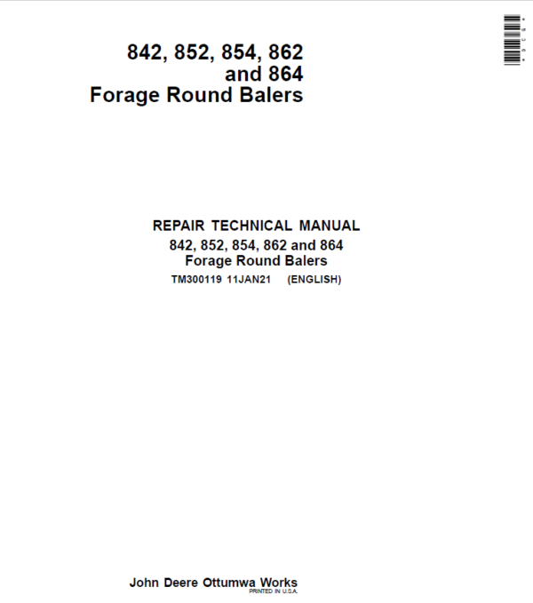
John Deere 842, 852, 854, 862, 864 Forage Round Baler Service Repair Manual (TM300119)
$50.00
Manual Included:
- Repair Technical Manual: (TM300119) – 1453 Pages
- Operator’s Manual: (OMCC59767) – 258 Pages
Specifications:
- Brand: John Deere
- Model: 842, 852, 854, 862, 864
- Type: Forage Round Baler
- Manuals: Repair Technical Manual and Operator’s Manual
- Publication Numbers: TM300119 and OMCC59767
- Language: English
- Format: PDF
- Description
- Reviews (0)
Description
Table of Content
Electrical System – Repair
Connectors
Sensors and Switches
Actuators
BaleTrak and BaleTrak Plus Monitor
Power Train
Walterscheid Powerline
Baler Main Drive Shaft
Shear Bolt Clutch
Walterscheid Slip Clutch
Cam-Type Cut Out Clutch
Gear Case
Chains
Sprocket Alignment
Braking System – Repair
Air Brakes
Hydraulic Brakes
Brake Shoe and Drum
Hydraulic System
Bale Density Control Valve
Hydraulic Cylinders
Hydraulic Hoses
Gate Lock Valve
Rotary Feeder Hydraulic Components
Miscellaneous
Axle
Gate Latch
Lubrication System – Repair
Drive Chain Lubrication
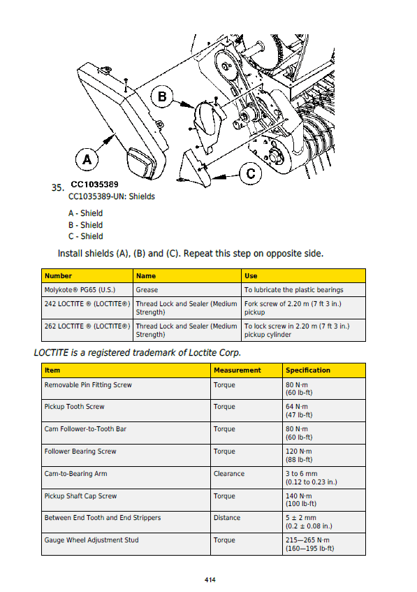
Pickup Repair
Rotary Feeding Device
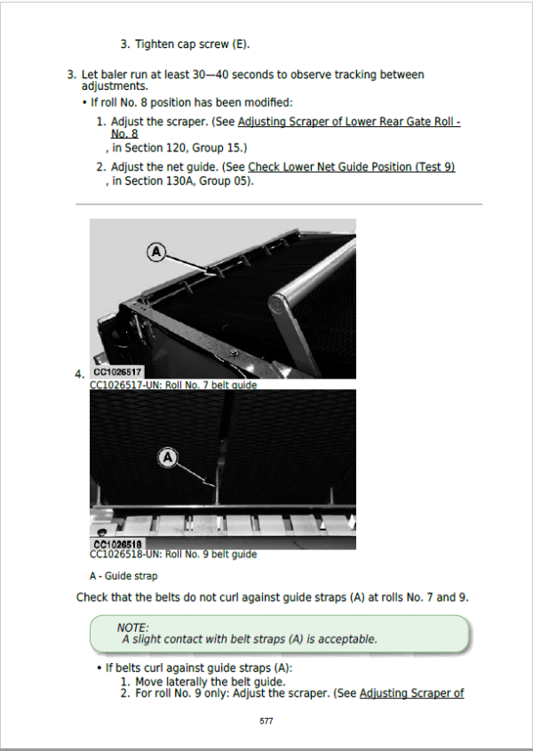
Bale Chamber
Net Tying System
Twine Tying System
Diagnostic Trouble Codes
Diagnostic Trouble Codes for ISOBUS Baler
Diagnostic Trouble Codes for BaleTrak Control
Description
Battery Voltage
Bale Size Potentiometer R2 or RB311
Right Bale Shape Potentiometer R4 or RB322
Left Bale Shape Potentiometer R3 or RB321
Twine Actuator M1
Net Actuator M2
Soft Core Valves Y1, Y5 and Y6
Pickup Solenoid Valve Y4
Knife Solenoid Valve Y3
Drop Floor Solenoid Valve Y2
Cleaning Auger S12
Lower Drive Roll RPM Sensor S6
Twine Pulley Sensors S7/S8
Net Cut Switch S4 or Sensor SB414
Right Gate Switch S1 or Sensor SB337
Left Gate Switch S2 or Sensor SB336
Oversize Bale Switch S3 or sensor SB317
Positive Analog Reference
EPROM
Observable Symptoms
Electrical System
General Information
Test Equipment
Electrical Diagram/Battery Wiring Harness
Electrical System/ELC Plus Monitor (Electronic Tying Control)
Electrical Diagram/ELC Plus Monitor (Electronic Tying Control)
Electrical System/BaleTrak Control
Electrical Diagram/BaleTrak Monitor
Diagnostic Modes/BaleTrak Monitor
Electrical Diagram/ISOBUS Baler
Diagnostic Tests – ISOBUS Baler
Diagnostic Modes/ISOBUS Baler
Advanced Machine Settings Mode/ISOBUS Baler
Connector and Component Information
Lubrication System – Operation and Tests
Air Brake System – Operation and Tests
Hydraulic Brake System – Operation and Tests
Hydraulic System – Operation and Tests
Safety
General Information
Bale Density/Gate Control – Description
Bale Density/Gate Control – Tests
Pickup Lift System (Baler without Precutter Device)
Rotary Feeder Hydraulic System without Precutter Device – Description
Rotary Feeder Hydraulic System without Precutter Device – Tests
Rotary Feeder Hydraulic System with Precutter Device – Description
Rotary Feeder Hydraulic System with Precutter Device – Tests
Net Tying – Operation and Tests
Special Tools
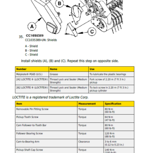
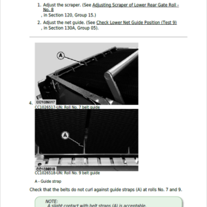
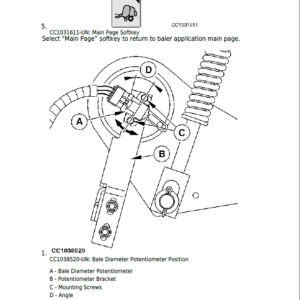
The Service Manual is intended to provide technical information, component specifications, troubleshooting and removal, disassembly and reassembly procedures for most of the major components of the machine.
Certain components such as the engine, felling head, and fire suppression system are covered in individual manuals provided by the respective manufacturers. For specifications, parts listings and servicing procedures these manuals should be obtained to supplement the Service Manual.
When practical the Service Manual lists likely causes of malfunctions, offers test procedures to verify causes and then illustrates the steps for the adjustment or repair procedure(s).
Be the first to review “John Deere 842, 852, 854, 862, 864 Forage Round Baler Service Repair Manual (TM300119)”
You must be logged in to post a review.




Reviews
There are no reviews yet.