Group 0250—Axle Shaft, Bearings, and Reduction Gears
Group 0260—Hydraulic System
Section 03—Transmission
Group 0300—Removal and Installation
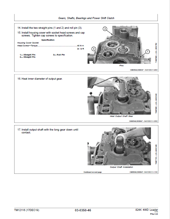
Group 0350—Gears, Shafts, Bearings and Power Shift Clutch
Group 0360—Hydraulic System
Section 04—Engine
Group 0400—Removal and Installation
Section 05—Engine Auxiliary System
Group 0505—Cold Start Aids
Group 0510—Cooling Systems
Group 0520—Intake System
Group 0530—External Exhaust Systems
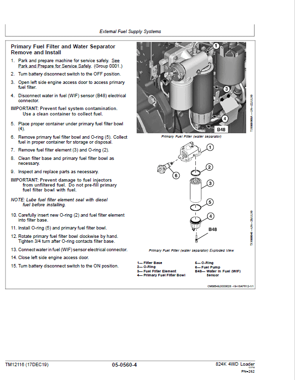
Group 0560—External Fuel Supply Systems
Section 07—Damper Drive
Group 0752—Elements
Section 09—Steering System
Group 0960—Hydraulic System
Section 10—Service Brakes
Group 1011—Active Elements
Group 1060—Hydraulic System
Section 11—Park Brake
Group 1111—Active Elements
Group 1160—Hydraulic System
Section 17—Frame or Supporting Structure
Group 1740—Frame Installation
Group 1746—Frame Bottom Guards
Group 1749—Chassis Weights
Section 18—Operator’s Station
Group 1800—Removal and Installation
Group 1810—Operator Enclosure
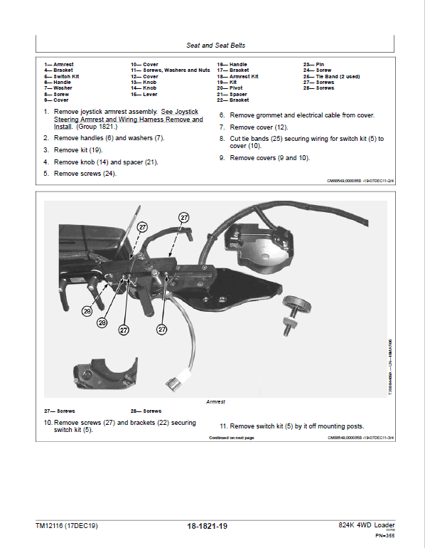
Group 1821—Seat and Seat Belts
Group 1830—Heating and Air Conditioning
Section 19—Sheet Metal and Styling
Group 1910—Hood or Engine Enclosure
Group 1921—Grille and Grille Housing
Section 31—Loader
Group 3102—Bucket
Group 3140—Frames
Group 3160—Hydraulic System
Section 99—Dealer Fabricated Tools
Group 9900—Dealer Fabricated Tools
Operation and Test Manual- TM12114
Section 9000—General Information
Group 01—Safety
Section 9001—Diagnostic Trouble Codes (DTC)
Group 10—Engine Control Unit (ECU) Diagnostic Trouble Codes
Group 20—Transmission Control Unit (TCU) Diagnostic Trouble Codes
Group 30—Vehicle Control Unit (VCU) Diagnostic Trouble Codes
Group 40—Sealed Switch Module (SSM) Diagnostic Trouble Codes
Group 50—Advanced Display Unit (ADU) Diagnostic Trouble Codes
Group 60—Radar Object Detection (ROD) Diagnostic Trouble Codes
Group 70—Ground Speed Radar (RDR) Diagnostic Trouble Codes
Group 80—Joystick Steering Valve (JSV) Diagnostic Trouble Codes
Group 90—Joystick Steering Controller (JSC) Diagnostic Trouble Codes
Group 100—Tire Pressure Monitoring (TPM) System Diagnostic Trouble Codes
Section 9005—Operational Checkout Procedure
Group 10—Operational Checkout Procedure
Section 9010—Engine
Group 05—Theory of Operation
Group 15—Diagnostic Information
Group 25—Tests
Section 9015—Electrical System
Group 05—System Information
Group 10—System Diagrams
Group 15—Sub-System Diagnostics
Group 16—Monitor Operation
Group 20—References
Section 9020—Power Train
Group 05—Theory of Operation
Group 15—Diagnostic Information
Group 20—Adjustments
Group 25—Tests
Section 9025—Hydraulic System
Group 05—Theory of Operation
Group 15—Diagnostic Information
Group 20—Adjustments
Group 25—Tests
Section 9031—Heating and Air Conditioning
Group 05—Theory of Operation
Group 15—Diagnostic Information
Group 25—Tests
Measurements in this manual are given in both metric and customary U.S. unit equivalents. Use only correct replacement parts and fasteners. Metric and inch fasteners may require a specific metric or inch wrench.
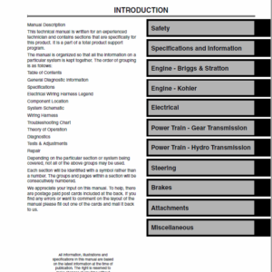
Technical manuals are divided in two parts: Repair and Operation and Tests. Repair sections tell how to repair the components. Operation and tests sections help you identify the majority of routine failures quickly. Information is organized in groups for the various components requiring service instruction. At the beginning of each group are summary listings of all applicable essential tools, service equipment and tools, other materials needed to do the job, service parts kits, specifications, wear tolerances, and torque values.
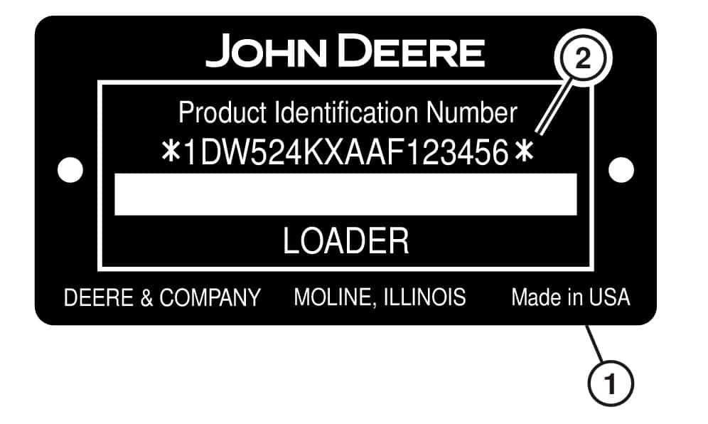
They are concise guides for specific machines. They are on-the-job guides containing only the vital information needed for diagnosis, analysis, testing and repair. The product identification number (PIN) plate (1) is located on the left side of machine in front of the steps. Each machine has a 17-character PIN (2) as shown on this plate.
Reviews
There are no reviews yet.
Be the first to review “John Deere 824K 4WD Engine T3 & S2 Loader Technical Manual (S.N 641970 – 664099)” Cancel reply
")
Reviews
There are no reviews yet.