")
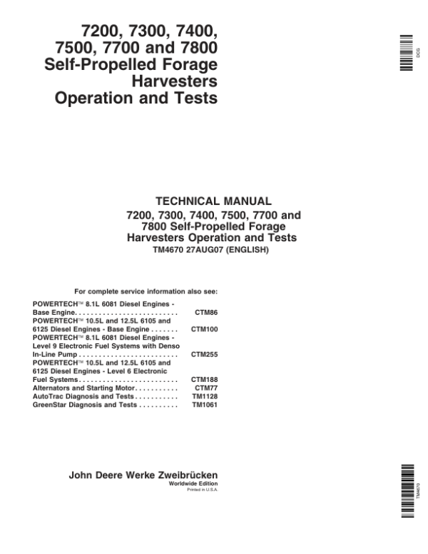
John Deere 7200, 7300, 7400, 7500, 7700, 7800 Harvester Repair Technical Manual (TM4670 & TM4668)
$65.00
Manual Included:
- Repair Technical Manual: 2295 Pages
- Operation and Test Manual: 3269 Pages
Specifications:
- Brand: John Deere
- Model: 7200, 7300, 7400, 7500, 7700, 7800
- Type: Self Propelled Forage Harvesters
- Manuals: Operation and Test, Repair Technical Manual
- Publication Numbers: TM4670 & TM4668
- Language: English
- Format: PDF
- Description
- Additional information
- Reviews (0)
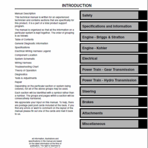
Description
Table of Content (Operation and Test Manual – TM4670)
SECTION 210—Safety and General Information 508099)
Group 05—Safety Information
Group 15—General Information
SECTION 211—Diagnostic Trouble Codes
Group AMS—AMS Diagnostic Trouble Codes
Group ARC—ARC Diagnostic Trouble Codes
Group ECUL9—ECU Diagnostic Trouble Codes (6125 JD Control Unit Level 9)
Group ECUL6—ECU Diagnostic Trouble Codes (6125 JD Control Unit Level 6)
Group ECU(CumminsMotor)—ECU Diagnostic Trouble Codes (Cummins Engine)
Group JDL—JDL Diagnostic Trouble Codes
Group OCP—OCP Diagnostic Trouble Codes
Group PTP—PTP Diagnostic Trouble Codes
Group RCP—RCP Diagnostic Trouble Codes
Group RDC—RDC Diagnostic Trouble Codes
Group RGC—RGC Diagnostic Trouble Codes
Group SIG—SIG Diagnostic Trouble Codes
Group SPF—SPF Diagnostic Trouble Codes
SECTION 212—Observable Symptoms
Group 20—Engine
Group 40—Electrical System
Group 50—ProDrive
Group 70—Hydraulic System
Group 90—Operator’s Station
SECTION 213—System Diagnostics
Group 40—Electrical System
Group 45—Electronics
SECTION 220—Engine
Group 05—Engine Specifications
Group 10—Operational Checks
Group 15—Tests And Adjustments
SECTION 230—Fuel, Air Intake and Cooling Systems
Group 15—Tests And Adjustments
Group 20—Theory of Operation
SECTION 240—Electrical System (up to Serial No
Group 10A—Power Distribution
Group 10B—Lighting System
Group 10C—Outlets
Group 10D—Wipers
Group 10E—Outside Mirrors
Group 10F—Ether Starting Aid
Group 10G—Horn
Group 10H—Engine Start
Group 10I—Air Conditioning System
Group 10J—Warning Devices and Monitors
Group 10K—Area Counter Functions
Group 10L—Electronically Controlled Lighting Functions
Group 10M—Cutterhead Control Functions
Group 10N—Engine Cooling Functions
Group 10P—Engine Speed Control Functions
Group 10Q—Feed Roll Control Functions
Group 10R—Header Control Functions
Group 10S—Kernel Processor Functions
Group 10T—Knife Sharpening Functions
Group 10U—Electronic Power Control Functions
Group 10V—Lubrication Control Functions
Group 10W—Metal Detector Functions
Group 10X—Drive Train Control Functions
Group 10Y—Row Guidance Functions
Group 10Z—Stationary Knife Adjust Function
Group 10AA—Spout Control Functions
Group 10AB—Trailer Functions
Group 10AC—System Interlock Functions
Group 10AD—On-Board Diagnostic Functions
Group 10AE—CAN Bus System Functions
Group 10AF—GreenStar Display/Moisture Sensor
Group 10AG—AutoTrac
Group 13—Functional Schematics – Sections 1 to 41
Group 15—Wiring and Harness Diagrams
Group 20—Wiring Diagrams, Connectors and Components
Group 21—Wiring Diagrams (Splices)
Group 25—Location of Wiring Harnesses
SECTION 241—Electrical System (from Serial No. 508100)
Group 10A—Power Distribution
Group 10B—Lighting System
Group 10C—Power Outlet Sockets
Group 10D—Wipers
Group 10E—Outside Mirrors
Group 10F—Ether Starting Aid
Group 10G—Horn
Group 10H—Engine Start
Group 10I—Air Conditioning System
Group 10J—Warning Devices and Monitors
Group 10K—Area Counter Functions
Group 10L—Electronically Controlled Lighting Functions
Group 10M—Cutterhead Control Functions
Group 10N—Engine Cooling Functions
Group 10P—Engine Speed Control Functions
Group 10Q—Feed Roll Control Functions
Group 10R—Header Control Functions
Group 10S—Kernel Processor Functions
Group 10T—Knife Sharpening Functions
Group 10U—Electronic Power Control Functions
Group 10V—Lubrication Control Functions
Group 10W—Metal Detector Functions
Group 10X—Drive Train Control Functions
Group 10Y—Row Guidance Functions
Group 10Z—Stationary Knife Adjust Function
Group 10AA—Spout Control Functions
Group 10AB—Trailer Functions
Group 10AC—System Interlock Functions
Group 10AD—On-Board Diagnostic Functions
Group 10AE—CAN Bus System Functions
Group 10AF—GreenStar Display/Moisture Sensor
Group 10AG—AutoTrac
SECTION 245—Control Units
Group 05—Operation and General Information on Diagnostics
Group 06—Test Equipment
Group 20—CAN Bus System
Group AMS—GreenStar Control Unit (AMS)
Group ARC—Armrest Control Unit (ARC)
Group ECU—Engine Control Unit (ECU)
Group JDL—JDLink Control Unit (JDL)
Group OCP—Overhead Control Panel Control Unit (OCP)
Group PTP—ProDrive Control Unit (PTP)
Group RCP—Corner Post Control Unit (RCP)
Group RDC—Rear Wheel Drive Control Unit (RDC)
Group RGCI—Row Guidance I Control Unit (RGC I)
Group RGCII—Row Guidance II Control Unit (RGC II)
Group SIG—Metal Detector Control Unit (SIG)
Group SPF—SPFH Main Control Unit (SPF)
Group SSU—SSU – AutoTrac Control Unit
SECTION 250—Power Train
Group 10—Operational Checks
Group 15—Tests and Adjustments for 3-Speed Transmission
Group 20—Theory of Operation of 3-Speed Transmission
SECTION 251—Power Train, ProDrive Transmission and Four-Wheel Drive
Group 05—Preliminary Checks
Group 10—Checks
Group 15—Tests And Adjustments
Group 20—Theory of Operation
SECTION 260—Brakes, Steering, Rear Axle
Group 10—Operational Checks
Group 15—Tests And Adjustments
Group 20—Theory of Operation
SECTION 261—Brakes, Steering, Row Guidance II, Rear Axle for Machines from Serial Number 508100
Group 05—Preliminary Checks
Group 10—Operational Checkout
Group 15—Tests And Adjustments
Group 20—Theory of Operation
SECTION 270—Hydraulic System
Group 05—General Information
Group 10—Hydraulic Circuit Diagrams
Group 15—Hydraulic Component Locations
Group 20—Hydraulic System Diagnostic Schematics
SECTION 271—Hydraulic System (Machines with ProDrive Transmission)
Group 05—General Information
Group 10—Hydraulic Circuit Diagrams
Group 15—Hydraulic Component Locations
Group 20—Hydraulic System Diagnostic Schematics
SECTION 290—Operator’s Cab
Group 10—Operational Checks
Group 15—Tests and Adjustments
Group 20—Theory of Operation
SECTION 299—Special Tools
Group 10—Special Tools and Test Equipment
SECTION 310—IVLOC Transmission
Group 05—General Information
Group 10—Operational Checks
Group 15—IVLOC Transmission Diagnostics
Group 20—Theory of Operation
Repair Technical Manual – TM4668
SECTION 05—Safety
Group 05—Safety Information
SECTION 10—General Information
Group 05—Fuel, Lubricants and Coolant
Group 10—Torque Values
Group 15—Serial Numbers
Group 20—Dimensions
SECTION 20—Engine
Group 05—Engine Removal and Installation
SECTION 30—Fuel, Air Intake and Cooling Systems
Group 05—Fuel Tank
Group 10—Air Intake System
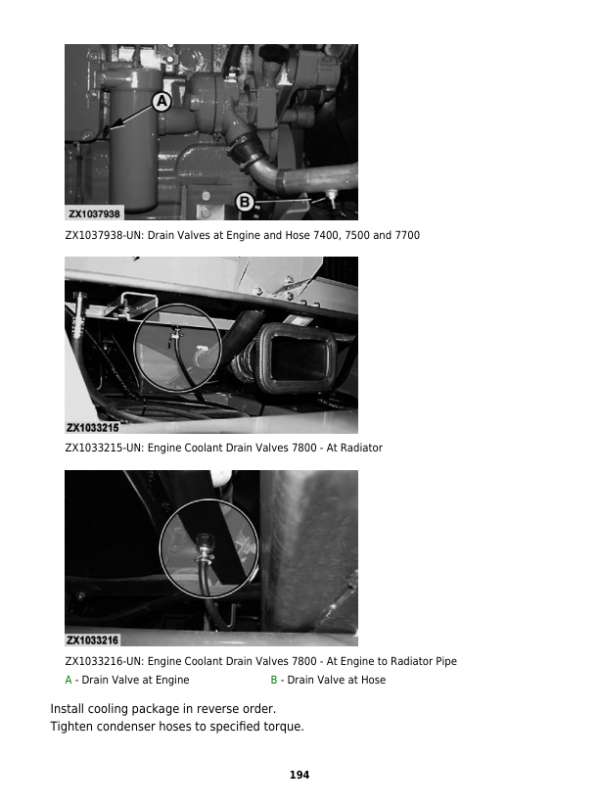
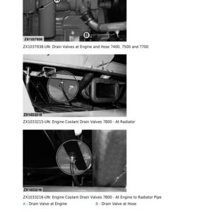
Group 15—Cooling System
SECTION 40—Electrical System
Group 05—Harness and Connector Repair
Group 10—Electrical System Components
SECTION 50—Power Train
Group 05—Main Drive Belt Replacement
Group 10—Bevel Gear Drive
Group 15—Transmission and Differential (Three-Speed Transmission)
Group 16—Transmission and Differential (ProDrive Transmission)
Group 20—Final Drives
Group 25—Hydrostatic Drive, Variable Pump (Three-Speed Transmission)
Group 26—Hydrostatic Drive, Variable Pump (ProDrive Transmission)
Group 30—Hydrostatic Drive, Fixed-Displacement Motor (3-Speed Transm.)
Group 31—Hydrostatic Drive, Variable-Displacement Motor (ProDrive)
Group 40—Rear Wheel Drive Axle—107 cc Motor Type
Group 41—Rear Wheel Drive Axle—140 cc Motor Type
Group 45—Rear Wheel Drive Axle, Variable-Displacement Motor
SECTION 60—Brakes, Steering and Rear Axle
Group 05—Brake Operation (Three-Speed Transmission)
Group 06—Brake Operation (ProDrive Transmission)
Group 10—Brakes (Three-Speed Transmission)
Group 11—Brakes (ProDrive Transmission)
Group 15—Hydrostatic Steering
Group 16—Row Guidance System (Gen. 1)
Group 17—Row Guidance System (Gen. 2)
Group 20—Rear Axle
SECTION 70—Hydraulic System
Group 05—Hydraulic Pressure Accumulators
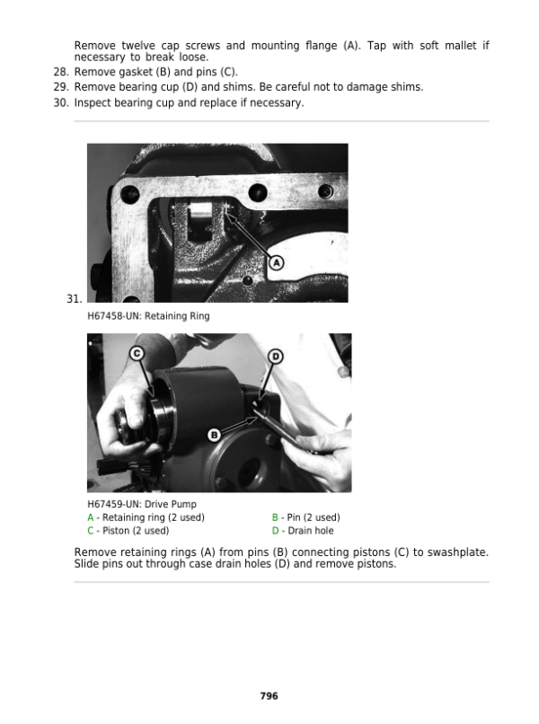
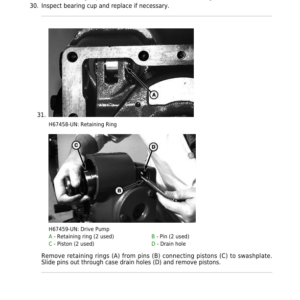
Group 10—Hydraulic Pumps
Group 15—Electromagnetic Control Valve
Group 20—Reverser Motor (Four-Speed LOC)
Group 25—Hydraulic Motor — Discharge Spout
Group 30—IV Length-of-Cut Transmission Motor
Group 35—IV Length-of-Cut Transmission Hydrostatic Pump
SECTION 80—Miscellaneous
Group 05—Central Lubrication System
SECTION 90—Operator’s Cab, Air Conditioning System
Group 05—Control Levers
Group 10—Cab Ventilation
Group 15—Operator’s Cab
Group 20—R134a Air Conditioning System
Group 25—Super Comfort Seat
SECTION 99—Special Tools
Group 05—Special Tools (Dealer Fabricated)
Group 10—Special Tools (Available as Spare Parts)
SECTION 100—Harvesting Units
Group 05—Harvesting Unit Cross Drive
Group 10—Harvesting Units
SECTION 110—Feeding System
Group 05—Four Speed Length-Of-Cut Transmission
Group 10—IV Length-Of-Cut Transmission
Group 15—Reverser Motor and Clutch (4-Speed L.O.C)
Group 20—Electrical Clutch (4-Speed L.O.C)
Group 25—Feed Roll Channel
Group 30—Feed Roll Assembly
Group 35—Locking Pawl (4-Speed L.O.C)
SECTION 120—Cutterhead Assembly
Group 05—Knife Sharpening Device
Group 10—Cutterhead
Group 15—Bottom and Outlet Bands
Group 20—Stationary Knife Removal and Installation
Group 25—Kernel Processor
Group 30—Power Chute
SECTION 130—Discharge Components
Group 05—Discharge Fan
Group 10—Blower Rotor and Rotor Bearings
Group 15—Discharge Spout
Additional information
| Serial | SN 010001-100000, SN 100001 – Current |
|---|
Be the first to review “John Deere 7200, 7300, 7400, 7500, 7700, 7800 Harvester Repair Technical Manual (TM4670 & TM4668)”
You must be logged in to post a review.

Reviews
There are no reviews yet.