Group 10—Engine Control Unit (ECU) Diagnostic Trouble Codes
Group 20—Engagement and Monitor Unit (EMU) Diagnostic Trouble Codes
Group 30—Hydraulic Control Unit (HCU) Diagnostic Trouble Codes
Group 40—Left Joystick Controller (JSL) Diagnostic Trouble Codes
Group 50—Right Joystick Controller (JSR) Diagnostic Trouble Codes
Group 60—Sealed Switch Module (SSM) Diagnostic Trouble Codes
Group 70—Vehicle Control Unit (VCU) Diagnostic Trouble Codes
Group 80—Rear Camera Display (VC1) Diagnostic Trouble Codes
Section 9005—Operational Checkout Procedure
Group 10—Operational Checkout Procedure
Section 9010—Engine
Group 05—Theory of Operation
Group 10—System Diagrams
Group 15—Diagnostic Information
Group 20—Adjustments
Group 25—Tests
Section 9015—Electrical System
Group 05—Theory of Operation
Group 10—System Diagrams
Group 15—Diagnostic Information
Group 16—Monitor Operation
Group 17—Diagnostic Test Box
Group 20—Adjustments
Group 25—Tests
Section 9020—Power Train
Group 05—Theory of Operation
Group 10—System Diagrams
Group 15—Diagnostic Information
Section 9025—Hydraulic System
Group 05—Theory of Operation
Group 10—System Diagrams
Group 15—Diagnostic Information
Group 20—Adjustments
Group 25—Tests
Section 9026—Hydrostatic System
Group 05—Theory of Operation
Group 10—System Diagrams
Group 15—Diagnostic Information
Group 25—Tests
Section 9031—Heating and Air Conditioning
Group 05—Theory of Operation
Group 10—System Diagrams
Group 15—Diagnostic Information
Group 25—Tests
Section 9900—Dealer Fabricated Tools
Group 99—Dealer Fabricated Tools
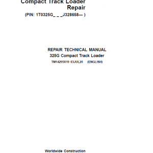
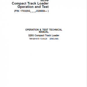
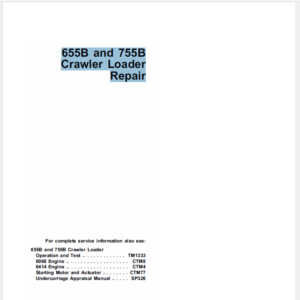
Technical manuals are divided in two parts: Repair and Operation and Tests.
-Repair sections tell how to repair the components.
-Operation and tests sections help you identify the majority of routine failures quickly.
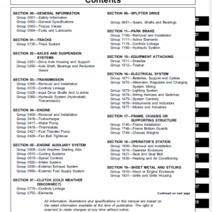
Information is organized in groups for the various components requiring service instruction. At the beginning of each group are summary listings of all applicable essential tools, service equipment and tools, other materials needed to do the job, service parts kits, specifications, wear tolerances, and torque values.
These are concise guides for specific machines. They are on-the-job guides containing only the vital information needed for diagnosis, analysis, testing and repair.
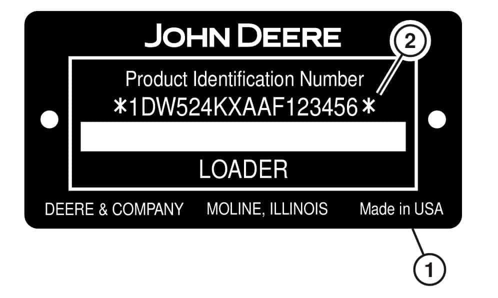
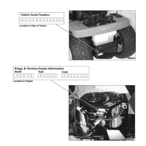
The product identification number (PIN) plate (1) is located on the left side of machine in front of the steps. Each machine has a 17-character PIN (2) as shown on this plate.
Reviews
There are no reviews yet.
Be the first to review “John Deere 325G Compact Track Loader Repair Technical Manual (S.N after J328658 – )” Cancel reply
")

Reviews
There are no reviews yet.