John Deere 310G Backhoe Loader Service Repair Manual

$52.00

Manual Included:

  • Technical Manual: 724 Pages (TM1886)
  • Operation and Test Manual: 854 Pages (TM1885)

Specifications:

  • Brand: John Deere
  • Model: 310G
  • Type: Loader
  • Manuals: Repair Technical and Operation and Test Manual
  • Publication Numbers: TM1886 and TM1885
  • Language: English
  • Format: PDF
Categories: ,

Description

Table of Contents

Repair Technical Manual (TM1886)

Section 00—General Information
Group 01—Safety Information
Section 01—Wheels
Group 0110—Powered or Non-Powered Wheels and Fastenings
Section 02—Axles and Suspension Systems
Group 0225—Input Drive Shafts and U-Joints
Group 0230—Non-Powered Wheel Axles
Group 0240—Powered Wheel Axle (MFWD)
Group 0250—Axle Shaft Bearings and Reduction Gears
Section 03—Transmission
Group 0300—Removal and Installation
Group 0315—Controls Linkage
Group 0325—Input Drive Shafts and U-Joint
Group 0350—Gears Shafts Bearings and Power Shift Clutch
Group 0360—Hydraulic System
Section 04—Engine
Group 0400—Removal and Installation
Section 05—Engine Auxiliary Systems
Group 0505—Cold Weather Starting Aid
Group 0510—Cooling System
Group 0515—Speed Controls
Group 0520—Intake System
Group 0530—Exhaust System
Group 0560—External Fuel Supply System
Section 06—Torque Converter
Group 0651—Turbine Gears and Shaft
Section 09—Steering System
Group 0960—Hydraulic System
Section 10—Service Brakes
Group 1011—Active Elements
Group 1060—Hydraulic System
Section 16—Electrical Systems
Group 1671—Batteries Support and Cables
Group 1672—Alternator Regulator and Charging System Wiring
Group 1674—Wiring Harness and Switches
Group 1676—Instruments and Indicators
Group 1677—Motors and Actuators
Section 17—Frames Chassis or Supporting Structure
Group 1740—Frame Installation
Group 1749—Chassis Weights
Section 18—Operator’s Station
Group 1800—Removal and Installation
Group 1810—Operator Enclosure
Group 1821—Seat and Seat Belt
Group 1830—Heating and Air Conditioning
Section 19—Sheet Metal and Styling
Group 1910—Hood and Engine Enclosure
Group 1913—Miscellaneous Shields
Group 1921—Grille and Grille Housing
Group 1927—Fenders
Section 20—Safety Convenience and Miscellaneous
Group 2001—Radio
Group 2004—Horn and Warning Devices
Section 21—Main Hydraulic System
Group 2160—Hydraulic System
Section 31—Loader
Group 3100—Loader
Group 3102—Bucket
Group 3115—Control Linkages
Group 3160—Hydraulic System
Section 33—Backhoe
Group 3302—Bucket
Group 3315—Control Linkage
Group 3340—Frames
Group 3360—Hydraulic System
Section 99—Dealer Fabricated Tool
Group 9900—Dealer Fabricated Tool


Operation and Test Manual (TM1885)

Section 9000—General Information
Group 01—Safety Information
Section 9005—Operational Checkout Procedure
Group 10—Operational Checkout Procedure
Section 9010—Engine
Group 05—Theory of Operation
Group 15—Diagnostic Information
Group 20—Adjustments
Group 25—Tests
Section 9015A—Electrical System (S.N. —951253)
Group 05—System Information
Group 10—System Diagrams
Group 15—Sub-System Diagnostics
Group 16—Monitor Operation
Group 20—References
Section 9015B—Electrical System (S.N. 951254—)
Group 05—System Information
Group 10—System Diagrams
Group 15—Sub-System Diagnostics
Group 16—Monitor Operation
Group 20—References
Section 9020—Power Train
Group 05—Theory of Operation
Group 15—System Diagnostic Information
Group 20—Adjustments
Group 25—Tests
Section 9025—Hydraulic System
Group 05—Theory of Operation
Group 15—Diagnostic Information
Group 20—Adjustments
Group 25—Tests
Section 9031—Heating and Air Conditioning
Group 05—Theory of Operation
Group 15—Diagnostic Information
Group 20—Adjustments
Group 25—Test

MEASUREMENTS in this manual are given in both metric and customary U.S. unit equivalents. Use only correct replacement parts and fasteners. Metric and inch fasteners may require a specific metric or inch wrench.

The Technical manuals are divided in two parts: Repair and Operation and Tests.
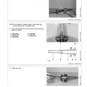
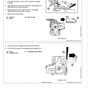
-Repair sections tell how to repair the components.
-Operation and tests sections help you identify the majority of routine failures quickly.

Please remember, the operator is the key to preventing accidents.
1. Headlights/Taillights. Two front halogen driving/work lights and two rear halogen work lights.
2. Signal/Warning Lights. Roof mounted turning signal lights and warning lights for on-road use.
3. ROPS Protection. Certified rollover protection structure surrounds the operator. Integral roof provides overhead protection.
4. Seat Position Sensor. An audio/visual warning alerts operator when FNR is in forward/reverse and the seat turned toward the backhoe position.
5. Interior Rear view Mirror. Offers the operator a view of activity behind him.
6. Handholds. Large and conveniently placed, make it easy to enter or exit the operator’s station.
7. Loader Boom Service Lock. Provided for working on or around this machine with the boom raised.
8. Engine Fan Guard. A secondary engine fan guard inside engine compartment encloses rotating fan blades.
9. Bypass Start Protection. Shielding over the starter solenoid helps prevent dangerous bypass starting.
10. Ground-Level Fuelling, Daily Service Checks.
Ground-level fuelling feature eliminates the need to climb on the machine to fuel it.
11. Steps. Wide, skid-resistant steps provide excellent footing for getting in/out of operator’s station.
12. Independent Parking/Secondary Brake.
Independent, electrically controlled, parking brake electrically engages when the engine is stopped.
13. Neutral Start. Prevents the engine from being started unless FNR control is in neutral.
14. Backup Alarm. Alerts bystanders when the machine is shifted into reverse.
15. Seat Belt Retractors. Seatbelt retractors help keep belts clean and convenient to use.
16. Exceptional Visibility. Views to either side and front or rear working tools are unrestricted.
17. Operator Manual Holder. A sealed manual holder keeps manual clean and dry.

Reviews

There are no reviews yet.


Be the first to review “John Deere 310G Backhoe Loader Service Repair Manual”