")
Hagie 204SP Detasseler Service Repair Manual (SN after 230001 -)
$46.00
Manual Included:
- Repair Technical Manual: 455 Pages
- Operation and Test Manual: 661 Pages
Specifications:
- Brand: John Deere
- Model: Hagie 204SP
- Serial Number: SN after 230000 –
- Type: Attachment
- Manuals: Operation and Test, Repair Technical Manual
- Publication Numbers: TM179119 & TM179019
- Language: English
- Format: PDF
- Description
- Reviews (0)
Description
Table of Content (TM179119 – Repair Manual)
Section 10—General Information
Group 05—Safety
Group 10—General Information
Group 15—Tune-Up and Adjustment
Group 20—Fuel and Lubricants
Section 20—Engine
Group 05—General Information
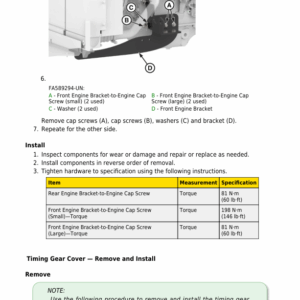
Group 10—Remove and Install
Section 30—Fuel, Air Intake, and Cooling Systems
Group 05—General Information
Group 10—Remove and Install
Group 20—Disassemble and Assemble
Group 30—Inspect
Section 40—Electrical
Group 05—General Information
Group 10A—Cab Electrical Components — Remove and Install
Group 10B—Control Units — Remove and Install
Group 10C—Engine, Fuel, Air Intake, and Cooling Electrical Components — Remove and Install
Group 10D—Hydraulic Electrical Components — Remove and Install
Group 10E—Lighting Electrical Components — Remove and Install
Group 10F—Powertrain Electrical Components — Remove and Install
Group 10G—Starting, Charging, and Power Distribution Components — Remove and Install
Group 10H—Toolbar Electrical Components — Remove and Install
Group 10I—Guidance Electrical Components — Remove and Install
Section 50—Power Train Repair
Group 05—General Information
Group 10—Remove and Install
Section 60—Steering and Brakes
Group 05—General Information
Group 10—Remove and Install
Group 20—Disassemble and Assemble
Section 70A—Hydraulic System
Group 05—General Information
Group 10—Remove and Install
Group 20—Disassemble and Assemble
Section 70B—Pneumatic System
Group 05—General Information
Group 10—Remove and Install
Section 80—Tool Bar
Group 05—General Information
Group 10—Remove and Install
Group 20—Disassemble and Assemble
Section 90—Operator Station
Group 05—General Information
Group 10A—Cab Components — Remove and Install
Group 10B—HVAC Components — Remove and Install
Group 20—Disassemble and Assemble
Group 30—Inspect
Section 300—Special Tools
Group 10—Service Tools and Kits
Table of Content (TM179019 – Diagnostic Manual)
Section 210—General Information
Group 05A—Safety
Group 05B—General References
Group 05C—References for Technical Information
Section 211—Diagnostic Trouble Codes
Group ECU—Engine Control Unit Diagnostic Trouble Codes
Group GR6—Starfire 6000 Diagnostic Trouble Codes
Group GR7—Starfire 7000 Diagnostic Trouble Codes
Group GR8—Starfire 7500 Diagnostic Trouble Codes
Group IR6—Implement Receiver Starfire 6000 Implement Diagnostic Trouble Codes
Group IR7—Implement Receiver Starfire 7000 Implement Diagnostic Trouble Codes
Group IR8—Implement Receiver Starfire 7500 Implement Diagnostic Trouble Codes
Group MG1—StarFire 6000 Integrated Receiver Diagnostic Trouble Codes
Group MG2—StarFire 7000 Integrated Receiver Diagnostic Trouble Codes
Group MG3—StarFire 7500 Integrated Receiver Diagnostic Trouble Codes
Group NAV—Diagnostic Trouble Codes
Group USC—Universal Steering Control Unit Diagnostic Trouble Codes
Group VTI—Virtual Terminal Implement Software Diagnostic Trouble Codes
Group VTV—Virtual Terminal Vehicle Software Diagnostic Trouble Codes
Section 212—System Diagnostics Access
Group 220—Engine System
Group 230—Fuel, Air Intake, and Cooling System
Group 240—Electrical
Group 245—Electrical Control Units
Group 260—Steering and Brakes System Group 270A—Hydraulic System Group 270B—Pneumatic System
Group 290—Cab System
Section 220—Engine
Group 05—General Information
Section 230—Fuel, Air Intake, Exhaust, and Cooling
Group 20—Theory of Operation
Group 30—Schematics
Group 50—Test and Adjustments Group 50A—Diagnostics
Section 240—Electrical
Group 05—General Information
Group 10—Operational and Preliminary Checks
Group 20A—Theory — Cab
Group 20B—Theory — Controller Area Network (CAN) Bus
Group 20C—Theory — Engine
Group 20D—Theory — Hydraulics
Group 20E—Theory — Lights
Group 20F—Theory — Powertrain
Group 20G—Theory — Start Charge and Power Distribution
Group 20H—Theory — Tool Bar
Group 20I—Theory — Guidance
Group 30A—Schematic — Cab
Group 30B—Schematic — Controller Area Network (CAN) Bus
Group 30C—Schematic — Engine
Group 30D—Schematic — Hydraulics
Group 30E—Schematic — Lights
Group 30F—Schematic — Powertrain
Group 30G—Schematic — Start Charge and Power Distribution
Group 30H—Schematic — Tool Bar
Group 30I—Schematic — Guidance
Group 50—Tests and Adjustments
Group 50A—Diagnostic — Cab
Group 50B—Diagnostic — Controller Area Network (CAN) Bus
Group 50C—Diagnostic — Engine
Group 50D—Diagnostic — Hydraulics
Group 50E—Diagnostic — Lights
Group 50F—Diagnostic — Powertrain
Group 50G—Diagnostic — Start, Charge, and Power Distribution
Group 50H—Diagnostic — Tool Bar
Group 50I—Diagnostic — Guidance
Section 245—Electrical Control Units
Group 05—General Information
Group 10A—Operational and Preliminary Checks
Group 10B—Interactive Tests and Calibrations
Group 10C—Programming Electronic Control Units
Group 20—Theory of Operation
Group 30—Schematic
Group 50A—Diagnostics
Section 249—Electrical System — Component Information
Group 05—General Information
Group 40W—Harnesses
Section 250—Powertrain
Group 05—General Information
Group 20—Theory of Operation
Group 50—Tests and Adjustments
Group 50A—Diagnostics
Section 260—Steering and Brakes
Group 05—General Information
Group 20—Theory of Operation
Group 50—Tests and Adjustments
Group 50A—Diagnostics
Section 270A—Hydraulics
Group 05—General Information
Group 20—Theory of Operation
Group 30—Schematics
Group 50—Tests and Adjustments
Group 50A—Diagnostics
Section 270B—Pneumatic System
Group 20—Theory of Operation
Group 30—Schematics
Group 50—Tests and Adjustments
Group 50A—Diagnostics
Section 279A—Hydraulics — Component Information
Group 05—General Information
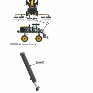
Group 40C—Cylinders, Actuators, and Pistons
Group 40D—Check Valves
Group 40F—Filters
Group 40G—Valve Blocks and Assemblies
Group 40H—Coolers
Group 40M—Motors
Group 40O—Orifices
Group 40P—Pumps
Group 40R—Reservoirs and Tanks
Group 40V—Valves
Group 40Y—Solenoid Valves
Section 279B—Pneumatic System — Component Information
Group 05—General Information
Group 40A—Accumulators
Group 40F—Filter
Group 40G—Assembly
Group 40P—Pumps
Group 40R—Reservoirs and Tanks
Group 40S—Switches
Group 40V—Valves
Section 290—Cab and Open Operator’s Station
Group 05—General Information
Group 10—Operational and Preliminary Checks
Group 20—Theory of Operation
Group 30—Schematics
Group 50—Test and Adjustments
Group 50A—Diagnostics
Section 299—Cab and Open Operator’s Station Component Information
Group 05—General Information
Group 40—Operator’s Station – Components
Section 300—Tools
Group 05—Recommended Tools
Group 10—Service Tools and Kits
Be the first to review “Hagie 204SP Detasseler Service Repair Manual (SN after 230001 -)”
You must be logged in to post a review.
Reviews
There are no reviews yet.