John Deere Modular telematics gateway (MTG) retrofitting to E-models
INSTALLATION GUIDE
MTG retrofitting to E-models
NOTE: Following list details the kit components. Consult your local dealer for up-to-date information.
|
Part |
Description |
Quantity |
|
F676315 |
Wiring harness |
1 |
|
F678407 |
Wiring harness (ethernet) |
1 |
|
L158947 |
Tape |
3 |
|
L174490 |
Washer, 4x16x1.6 |
4 |
|
L175903 |
Screw, pan head M6x20 Torx |
4 |
|
L201396 |
Grommet |
1 |
|
L202303 |
Screw, hexagon flanged |
4 |
|
L206439 |
Socket, self adhesive |
2 |
|
L209976 |
Cover, GPS+MTG antenna |
1 |
|
L210303 |
Bracket |
1 |
|
L61335 |
Washer |
4 |
|
L79493 |
Push nut, M6 |
4 |
|
PFA10255 |
MTG controller |
1 |
|
R260093 |
Tape, sealing band |
2 |
Note that kit doesn’t include the antenna. This needs to be ordered separately: EU antenna PFA10060
NA antenna AT374900
MTG RETROFIT FOR AN OLD E-CABIN
IMPORTANT: Read the safety instructions. See the separate safety section at the beginning of the instruction material.
Step 1
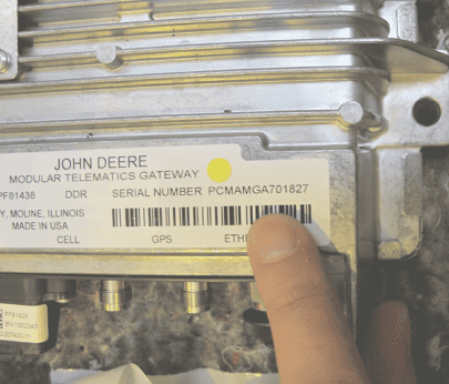
Prior to any retrofitting work, check the MTG box serial number and write it down. Serial number is needed for the activation procedure in Stellar support.
Step 2
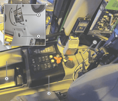
Remove the dashboard (1), the right-hand storage box cover (2) and the right side top trim panel (3).
|
Application |
Tool |
Size |
|
Dashboard |
Torx |
T15 |
|
Storage box cover |
Phillips screwdriver |
– |
|
Trim panel |
Torx |
T15 |
Step 3
Remove the right side rear trim panel covers (4). Unscrew the attachment screws by hand.
Step 4
Take off the first aid kit from the holding strips and remove the C-pillar trim panel (5).
|
Application |
Tool |
Size |
|
Trim panel |
Torx |
T15/T30 |
Step 5
Attach (glue) the drilling template to the front section of the right-hand side storage box. Drill holes (3 x 9mm) for the MTG module using the drilling template.
NOTE: Remove the possible USB hub aside before drilling.
|
Application |
Tool |
Size |
|
Holes for the MTG box |
Hard metal bit |
9 mm |
Step 6
Place wooden blocks under the roof trim panel beneath the drilling point for the feedthrough hole. This should be done to protect the roof trim panel.
Remove any existing protective casing from the cabin roof. Drill the feedthrough hole (36 mm) to the location indicated in the picture.
Clean any debris from around the through hole and remove the wooden blocks after drilling.
|
Application |
Tool |
Size |
|
Protective casing on the cabin roof |
Torx |
T30 |
|
Feedthrough hole |
Hard metal bit |
36 mm |
Step 7
Prepare the cabin roof for the antenna installation:
- Remove the possible GPRS module cover (6). Clean the installation area with cleansing agent.
- Attach the sealing tape to the edges of the new protective cover (7). Thread the rubber flange to the antenna cable with self-locking pliers.
|
Application |
Tool |
Size |
|
GPRS cover |
hex socket |
10 mm |
|
Feedthrough flange |
Self-locking pliers |
– |
Step 8
Attach the cellular antenna (8) by placing the adhesive surface to the correct position on the cabin roof. Use the protective cover as a reference to position the cellular antenna to the upper right corner. Refer to the image for correct placing.
Guide the antenna wires (9) to go through the feedthrough hole and direct the wiring from behind the right rear speaker to the C-pillar using the existing wires as support. Set the feedthrough flange (10) to the hole and finish off the feedthrough area and remaining holes with silicone paste.
NOTE: Do not bend the antenna wires too much!
Step 9
Install the new protective cover (7) into place. Note to use the required plastic washers underneath the attachment screws and rubber padding underneath the fastening plate.
|
Application |
Tool |
Size |
|
Attachment screws |
Torx |
T30 |
|
Fastening plate |
Ring spanner |
18 mm |
Step 10
Guide the antenna wires (9) to go down the C-pillar along the existing wiring and then along the right side so that the wires go under the right-hand side storage box to the front. Attach wires to the existing wiring with cable ties.
Step 11
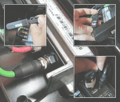
Connect the antenna wires (9), CAN branch circuit (11) and Ethernet network cable (13) to the MTG terminal (12).
Step 12
Attach the MTG terminal (12) to the front side of the right-hand side storage box by tightening the screws from inside the storage box.
|
Application |
Tool |
Size |
|
MTG terminal |
Ring spanner |
13 mm |
Step 13
Connect the MTG terminal to the base machine CAN bus and power using the CAN branch circuit:
Connect CAN wiring from XC25 to XC5.1 and XC5.2. Connectors are located in the right back corner of the cabin.
Connect power from X66 to connector X152A and duplicate the connection X130. Connectors are located under the dashboard.
Step 14
Connect the Ethernet network cable to the onboard PC:
Connect Ethernet cable from MTG terminal to D-Link adapter.
Connect the D-Link adapter to USB connection cable and lead the connection cable to the USB hub.
Step 15
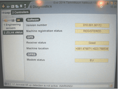
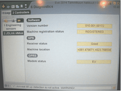
Use TimberMatic™ to check that MTG terminal can be found on the CAN bus. TimberMatic page
6.2.C.2 can be used for this after the release of TimberMatic version 1.19.
Proceed with MTG terminal activation in Stellar Support website. Refer to the separate JDLink user manual for activation steps.
Install all trim panel covers and other components in reverse order.
MTG RETROFIT FOR AN UPDATED E-CABIN (IT4)
IMPORTANT: Read the safety instructions. See the separate safety section at the beginning of the instruction material.
Step 1
Prior to any retrofitting work, check the MTG box serial number and write it down. Serial number is needed for the activation procedure in Stellar support.
Step 2
Open the right-hand storage box cover (1) and remove the dashboard (2).
Remove the right side rear trim panel cover (3). Unscrew the attachment screws by hand. Remove the C-pillar trim panel (4) and loosen the roof panel (5) from behind the first aid kit.
|
Application |
Tool |
Size |
|
Dashboard |
Torx |
T15 |
|
C-pillar trim panel and roof panel |
Torx |
T25/T30 |
Step 3
Prepare the cabin roof for the antenna installation: Remove the old cover from the cabin roof.
Clean the installation area with cleansing agent.
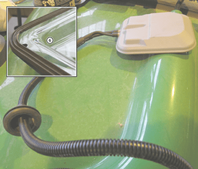
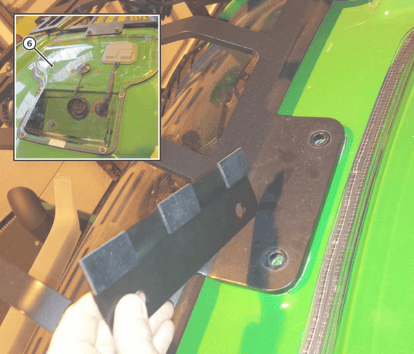
Attach the sealing tape to the edges of the new protective cover (6). Thread the rubber flange to the antenna cable with self-locking pliers.
|
Application |
Tool |
Size |
|
Feedthrough flange |
Self-locking pliers |
– |
Step 4
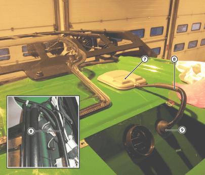
Attach the cellular antenna (7) by placing the adhesive surface to the correct position on the cabin roof. Use the protective cover as a reference to position the cellular antenna to the upper right corner. Refer to the image for correct placing.
Guide the antenna wires (8) to go through the feedthrough hole and direct the wiring to the C- pillar using the existing wires as support. Set the feedthrough flange (9) to the hole.
NOTE: Do not bend the antenna wires too much!
Step 5
Install the new protective cover (6) into place. Note to use the required plastic washers underneath the attachment screws and rubber padding underneath the fastening plate.
|
Application |
Tool |
Size |
|
Attachment screws |
Torx |
T30 |
|
Fastening plate |
Ring spanner |
18 mm |
Step 6
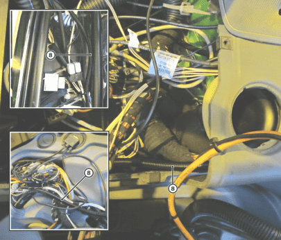
Guide the antenna wires (8) to go down the C-pillar along the existing wiring and then along the right side so that the wires go under the dashboard. Attach wires to the existing wiring with cable ties.
Step 7
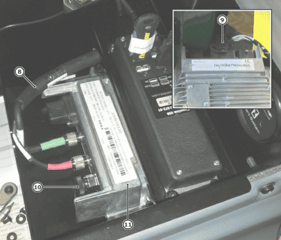
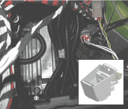
Connect the antenna wires (8), CAN branch circuit (9) and Ethernet network cable (10) to the MTG terminal (11).
Open the first support plate from the right-hand storage box and attach the MTG terminal to the plate.
|
Application |
Tool |
Size |
|
Support plate |
Torx |
T15 |
|
MTG terminal |
Ring spanner |
13 mm |
Step 8
Place the plate holding the MTG terminal (11) to the original position.
|
Application |
Tool |
Size |
|
Support plate |
Torx |
T15 |
Step 9
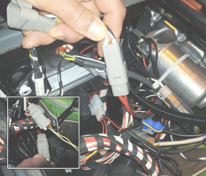
Connect the MTG terminal to the base machine CAN bus and power using the CAN branch circuit:
Connect the branch circuit to connectors X66 and XC25. Note that connectors are located either under the dashboard or in the back right corner.
Step 10
Connect the Ethernet network cable to the onboard PC:
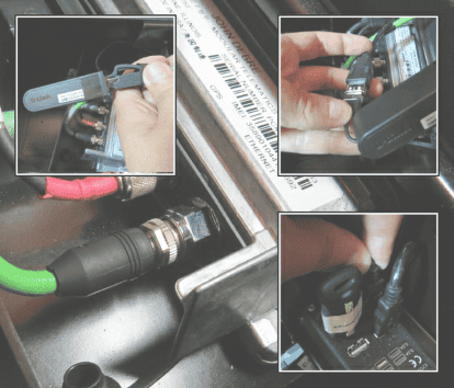
Connect Ethernet cable from MTG terminal to D-Link adapter.
Connect the D-Link adapter to USB connection cable and lead the connection cable to the USB hub.
Step 11
Use TimberMatic™ to check that MTG terminal can be found on the CAN bus. TimberMatic page
6.2.C.2 can be used for this after the release of TimberMatic version 1.19.
Proceed with MTG terminal activation in Stellar Support website. Refer to the separate JDLink user manual for activation steps.
Install all trim panel covers and other components in reverse order.


Leave a Reply
You must be logged in to post a comment.