
Hyundai HA30, HA30A, HA45, HA45A Articulated Dump Truck Service Repair Manual
$38.00
Manual Included:
- Service Repair Manual: 1133 pages
- Operators Manual: 284 Pages
Specifications:
- Brand: Hyundai
- Model:HA30, HA30A, HA45, HA45A
- Type: Articulated Dump Truck
- Manuals: Service Repair and Operators Manual
- Language: English
- Format: PDF
- Description
- Reviews (0)
Description
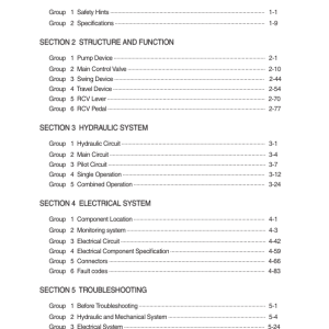
Table of Contents:
Foreword
Doosan ADT Payload Policy
Torque limit table
Types of sealing-/locking compounds and lubricants
Safety in workshop
Working on machine
Personal Protective Equipment (PPE)
Vibration
Injurious noise
Organic solvent
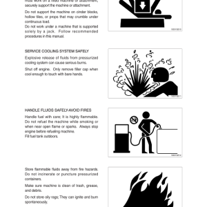
Fuelling
Fire and Explosion Prevention
Fire and explosion risks
In case of Fire
Coolant
Refrigerant
Air pollution
Operation in extreme conditions
Liquid or gas under high pressure
Asbestos
Lead
Battery hazard prevention
Disposal of hazardous materials
Jacked up vehicle or bodywork
Crushing and Cutting Danger
Heavy units
More than one person working with the same object
Involuntary start of electric motors etc.
Rotating parts
Splinters, flying object When using certain tools
Springs under load
Precautions for disassembly and assembly
HA30 – HA45 Final S2 – 1 Engine PDE (VERKST-BOK – 1132510 – 1 – A)
Engine identification
Removal of engine assembly
Lifting the engine
Starting the engine
Important information about the fuel
Fuel system Tier2 (PDE)
Schematic diagram of the fuel system Tier2
Overflow valve
General
Fuel
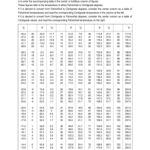
Temperature dependency of the fuel
Fuel filter
Changing the fuel filter
Water separating prefilter PDE
Changing the water separating fuel filter
Bleeding the fuel system
Feed pump
Renewing the control unit
Cylinder head – PDE System Tier2
Cylinder head, parts view. PDE Tier2
Special tools
Valve mechanism
Dismantling
Renewing the valve stem seal
Replacement of valve seats
Machining the valve seats insert
Renewing the valve guides
Renewing PDE unit injector sleeves
Assembly
Fitting
Valve adjustment DC9 / DC13 with XPI
Adjustment tables DC9 / DC13
Checking and adjusting the unit injectors
Turbocharger
Measuring radial clearance and axial clearance
Renewing the turbocharger
General
Changing oil filter
Oil analysis
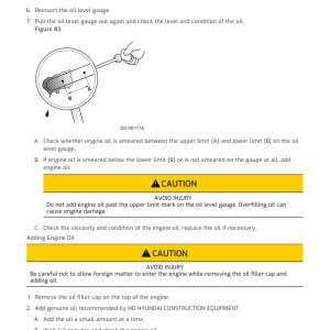
Checking oil level
Changing the oil
Special tools
Pistons and cylinder liners
Special tools
Connecting rods
Removing and dismantling connecting rods and pistons
Renewal of bearing bushing in connecting rod
Pistons
Assembling piston and connecting rod
Cylinder block
Cylinder liner
Removing the cylinder liners
Measuring the cylinder liner height
Measuring the cylinder wear ridge and cylinder bore
Fitting the cylinder liners
Fitting the piston and connecting rod
Flywheel and flywheel housing
Special tools
Removing the flywheel
Renewing the rear crankshaft seal
Removing the flywheel housing
Fitting flywheel housing
Fitting the flywheel
Flexible coupling
Safety instructions
Functional description
Disassembly and dismantling the coupling
Assembling the coupling 7×1126; 8×1128.
Installation instructions
Friction disk, friction ring
Timing gear – 13 and 9 litre
Gear drive
Belt drive coolant pump, generator and AC compressor
Checking the drive belt
Check for leaks
Renewing the seal in the front cover
Crankshaft damper
Timing gear, exploded view
Special tools
Intermediate gear
Renewal of bearing in intermediate gear for the camshaft
Camshaft gear
Crankshaft gear
Camshaft
Replacement of camshaft bearing
Crankshaft
Removal
Fitting
Adjust – Machining the crankshaft
Lubrication system
General
Oil pump
Lubrication oilways
Oil pressure
Oil cooler, engine
Oil cooler view See 010009
Renewing seals and leakage testing
Oil filter
Centrifugal oil cleaner
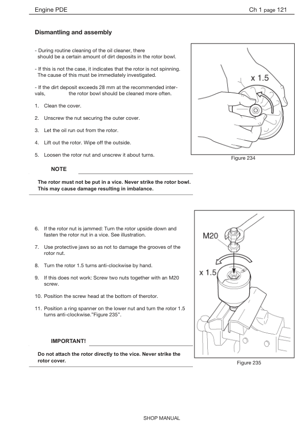
Dismantling and assembly
Operational testing of the centrifugal oil cleaner
Oil mist separator
General
High levels of oil carryover
Crankcase pressure measurement
Oil mist separator exploded view
Oil mist separator disassemble
Check – Rotational speed on oil mist separator
Alternator 100 A
Check
Output test
Renewal – Bearing and carbon brushes
Oil pump, brake cooling
Exploded view
Disassemble and overhaul the oil pump
Checking and renewing parts
Oil circulate pump assemble.
Renewing the gasket
Cooling fan
View of the radiator system
Cooling system
Principal view of the cooling system
Circulation
Coolant
Checking coolant level
External leakage
Internal leakage
Checking the antifreeze level
Changing coolant
Filling coolant
Cleaning the cooling system
Disassemble the cooling unit
Disassemble the cooling unit
Thermostat and thermostat housing
Thermostat
Coolant pump
External cleaning
Internal cleaning
Technical data DC13 with PDE
General data
Technical data DC9 with PDE
General data
Troubleshooting SDP3 / Canbus
To do:
Troubleshooting – basic info
Diagnostic procedure
Use of diagnostic kit
Connection point Canpc + OBDII connector
Can bus overview
SDP3 Scania diagnostic
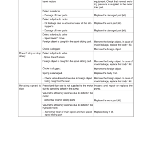
Troubleshooting Manual
White smoke
White smoke, water vapour
Black smoke on starting
Blue smoke
Fuel in the oil
Oil in coolant
Coolant/water in oil
Low oil pressure
High oil pressure (engine warmed up)
Abnormal wear (liner, piston rings, etc.)
Vibration, no driven components engaged
Vibration when the clutch or reverse gear is engaged
Vibration when alternator is in operation
Engine speed hunting – single-speed engines with RQ governor
Engine speed hunting – single-speed engines with RSV governor
Delivery pipe fractures
External corrosion on cylinder liner
Engine difficult to start
Fluid stroke
Knocking/noise
High oil consumption
High fuel consumption
Low compression
Low engine output
Hot engine
Cold engine
Coolant loss
Polluted coolant
High oil temperature
High exhaust temperature
Low charge air pressure
Low fuel pressure
Low system voltage
High system voltage
External oil leakage
External fuel leakage
External coolant leakage
Oil pressed out via crankcase ventilation
Turbocharger breakdown
Compressed air system
HA30 – HA45 Final S2 – 1 Engine XPI (VERKST-BOK – 1132587 – 1 – A)
Engine identification
Removal of engine assembly
Lifting the engine
Starting the engine
XPI Fuel system DA30/45
Route of the fuel on 9 and 13 litre engines
Fuel filter and water separation filter
Changing the fuel filter
Water separating prefilter
Changing the water separating fuel filter
Bleeding the fuel system using a hand pump
Overflow valve
Fuel system components
Schematic diagram of the fuel system
Important information about the fuel
Exhaust system XPI T4F
Introduction system overview
Overview – Control system for exhaust gas aftertreatment
Control unit EEC3
System overview for mechanics
System overview for electronics
Ad blue filter change
Reductant dozer
Start-up instruction for new SCR Pump
Reductant pump, function
EGR valve and actuator removal
Checking the control cylinder
Leak testing the EGR cooler
Renewing the control unit
Common rail injectors Tier4/XPI
Cylinder head – XPI system Tier4
Cylinder head, parts view. XPI system Tier4
Injector Scania XPI
Valve adjustment DC9 / DC13 with XPI
Adjustment tables DC9 / DC13
Turbocharger
Measuring radial clearance and axial clearance
VGT (Variable geometry turbo)
VGT Removal
VGT fitting
General
Changing oil filter
Oil analysis
Checking oil level
Changing the oil
Special tools
Pistons and cylinder liners
Special tools
Connecting rods
Removing and dismantling connecting rods and pistons
Renewal of bearing bushing in connecting rod
Pistons
Assembling piston and connecting rod
Cylinder block
Cylinder liner
Removing the cylinder liners
Measuring the cylinder liner height
Measuring the cylinder wear ridge and cylinder bore
Fitting the cylinder liners
Fitting the piston and connecting rod
Flywheel and flywheel housing
Special tools
Removing the flywheel
Renewing the rear crankshaft seal
Removing the flywheel housing
Fitting flywheel housing
Fitting the flywheel
Flexible coupling
Safety instructions
Functional description
Disassembly and dismantling the coupling
Assembling the coupling 7×1126; 8×1128.
Installation instructions
Friction disk, friction ring
Timing gear – 13 and 9 litre with XPI
Gear drive
Belt drive coolant pump, generator and AC compressor
Checking the drive belt
Check for leaks
Renewing the seal in the front cover
Crankshaft damper
Timing gear, exploded view
Special tools
Intermediate gear
Camshaft gear
Crankshaft gear
Camshaft
Replacement of camshaft bearing
Crankshaft
Removal
Fitting
Adjust – Machining the crankshaft
Lubrication system
General
Oil pump
Lubrication oil-ways
Oil pressure
Oil cooler, engine
Oil cooler view
Renewing seals and leakage testing
Oil filter
Centrifugal oil cleaner
Dismantling and assembly
Operational testing of the centrifugal oil cleaner
Oil mist separator
General
High levels of oil carryover
Crankcase pressure measurement
Oil mist separator exploded view
Oil mist separator disassemble
Check – rotational speed on oil mist separator
Alternator 100 A
Check
Output test
Renewal – bearing and carbon brushes
Oil pump, brake cooling circulate
Exploded view
Disassemble and overhaul the oil pump
Checking and renewing parts
Oil circulate pump assemble.
Renewing the gasket
Cooling fan
View of the radiator system
Cooling system
Principal view of the cooling system
Circulation
Coolant
Checking coolant Level
External leakage
This manual has been prepared as an aid to improve the quality of repairs by giving the serviceman an accurate understanding of the product and by showing him the correct way to perform repairs and make judgements. Make sure you understand the contents of this manual and use it to full effect at every opportunity.
This service manual mainly contains the necessary technical information for operations performed in a service workshop.
Be the first to review “Hyundai HA30, HA30A, HA45, HA45A Articulated Dump Truck Service Repair Manual”
You must be logged in to post a review.


Reviews
There are no reviews yet.