

Hyster C1.05B, V35XMU Man-Up Turret Trucks A468 Series Repair Manual
$45.00
Repair Manual for Hyster A468 Series, Models: C1.05B (V35XMU)
Format: PDF
English
- Hyster C1.05B, V35XMU Man-Up Turret Trucks A468 Series Repair Manual: 883 Pages
- Description
- Reviews (0)
Description
Hyster C1.05B, V35XMU Man-Up Turret Trucks A468 Series Repair Manual
Repair Manual for Hyster A468 Series, Models: C1.05B (V35XMU)
Format: PDF
English
- Hyster C1.05B, V35XMU Man-Up Turret Trucks A468 Series Repair Manual: 883 Pages
Hyster A468 Series, Models: C1.05B (V35XMU) Manual Table Of Content:
1.0 Introduction
Section: Truck Installation
1.0 Introduction
1.1 Vna Instalation
1.2 Vna Unpacking And Set Up
1.3 Vna Delivery
2.0 Vna Removal From Container / Truck
3.0 Vna Stand Up Procedure
4.0 Lower Cab After Stand Up
5.0 Installation Of Attachment
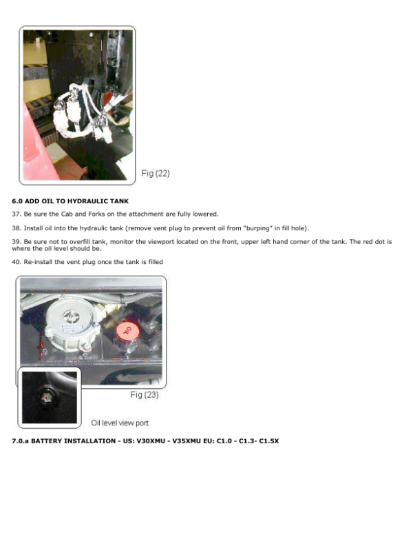
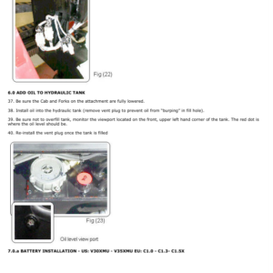
6.0 Add Oil To Hydraulic Tank
7.0.A Battery Installation Us: V30Xmu – V35Xmu Eu: C1.0 – C1.3 – C1.5B
7.0.B Battery Installation Us: V40Xmu Eu: C1.8X
8.0 Installation In Aisle
8.1 Load Unit Deposit Adjustment
8.2 Important (Guide Rollers / Wire Guidance)
9.0 Operator Training
Section: Electrical System
1.0 Electrical Compartment Arrangement Models V30Xmu – V35Xmu – C1.0 – C1.3 – C1.5B
1.0.1 Electrical Compartment Arrangement Models V40Xmu – C1.8X
1.1 Description Of Components
1.1.1 Photocells
1.1.1A Photocell Adjustment
1.1.1B Malfunction Caused By Incorrect Adjustment
1.1.2 Throttle Assembly
1.1.3 Battery Discharge Indicator (Bdi)
1.1.3A Lock Out Level Adjustment
1.1.3B Bdi Troubleshooting
1.1.4 Dc / Dc Converter
1.2 Table Of Electrical System Components
2.0 Traction Motor Electronic Control
2.0.1 Introduction
2.1 Definition Of The Truck Direction Of Travel
2.2 Controller General Features
2.3 Controller Functional Features
2.4 Controller Diagnostics
2.5 Chopper H2B Mechanical Diagram
2.6 Connectors
2.7 Connector Inconnector “E” Input Description
2.9 Basic Diagram Of The Traction Controller Connections
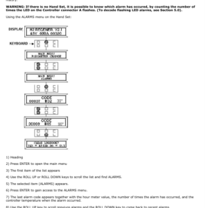
3.0 Hand Set
3.0.1 Introduction
3.2 Use Of The Hand Set
3.2.1 Connection To Controller
4.0 Console Function Chart – Traction Motor Controller
4.1 Controller Programming
4.1.0 Configuration Menu
4.1.1 Config. Menu / Set Model
4.1.2 Config. Menu / Set Options
4.1.3 Config. Menu / Adjustment
4.1.4 Main Menu / Paramet. Change
4.1.5 Main Menu / Tester
4.1.6 Main Menu / Save Parameter
4.1.7 Main Menu / Restore Param.
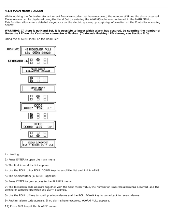
4.1.8 Main Menu / Alarm
4.1.9 Main Menu / Program Vacc
4.1.9 Main Menu / Program Vacc
4.2 Configuration Tables For Traction Controller
4.3 Programming Levels Correspondence Table
4.4 Set Up Of A New Controller Before Operation
5.0 Troubleshooting
5.1 Decoding Diagnostic Led Alarm Codes For Traction Controller
5.2 Decoding Hand Set Alarms For Traction Controller
6.0 Pump Motor Controller – Description
6.1 Controller Functional Features
6.2 Pump Motor Controller Circuit
6.3 Pump Motor Controller Connectors
6.4 Connector Input Descriptions (Except E)
6.5 Connector “E” Input Description
6.6.A Console Function Chart – Pump Motor Controller
6.6 Hand Set Programming Of The Pump Motor Controller
6.6.1 Configuration Menu
6.7 Configuration Table – Pump Motor Controller
6.8 Parameter Value Versus Programmed Level Table
6.14 Troubleshooting
6.14.1 Decoding Diagnostic Led Alarm Codes For Pump Controller
6.14.2 Decoding Hand Set Alarms For Pump Motor Controller
7.0 Configuration Tables – Eps Electric Power Steering Controller
7.1 Eps Configuration With Smart Steer (Pot) Steering
7.2 Eps Configuration With Tacho Generator Steering
Section: Plc
1.0 Standard Interlock Functions
2.0 Enable Function Management
2.1 Description Of The System That Runs The Enables Plc (Programmable Logic Controller)
2.2 General Characteristics
3.0 Programming
4.0 Electric Adjustment Of The Cab And Auxiliary Mast Lowering Proportional Electro-Hydraulic Valves
5.0 Plc Digital Input / Output Reference Eu / Us Versions
5.1.A Plc Truth Table And Interface Relay Board (Us Version Only)
5.1.B Plc Truth Table And Interface Relay Board (Eu Version Only)
6.0 Removing/Installing The Plc
7.0 Plc Battery Function And Changing
8.2 Procedure For Changing Fuses
Section: Diagnostics
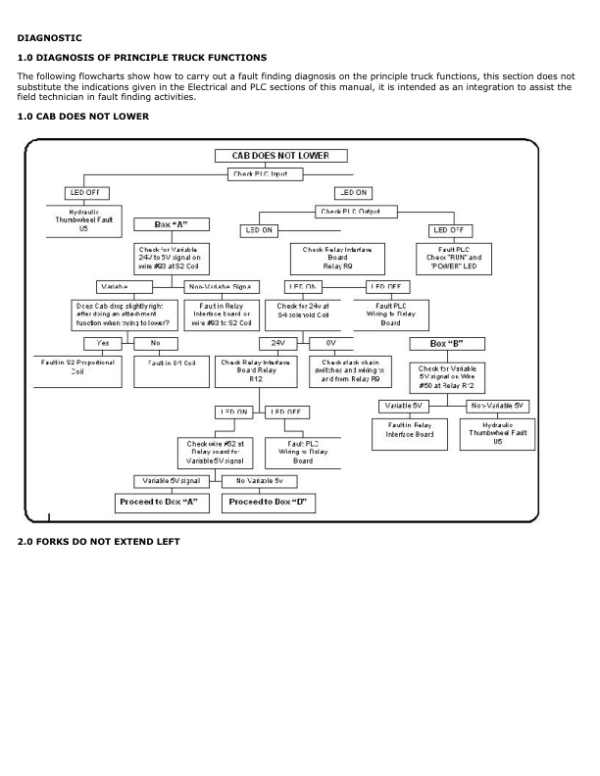
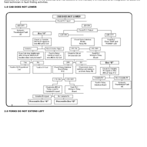
1.0 Cab Does Not Lower
2.0 Forks Do Not Extend Left
3.0 Forks Do Not Extend Right
4.0 Forks Do Not Lower
5.0 Forks Do Not Raise
6.0 Forks Do Not Retract From Left
7.0 Forks Do Not Retract From Right
8.0 Forks Do Not Rotate Left
9.0 Forks Do Not Rotate Right
10.0 High Temperature
11.0 Mini Mast Does Not Traverse Left
12.0 Mini Mast Does Not Traverse Right
13.0 Sync Cab / Forks Do Not Lower
14.0 Sync Traverse / Rotate Does Not Work
15.0 Truck Does Not Travel
Section: Slow Down / Stop
1.0 Automatic Slow Down And Stop System Description
1.1 Magnet Installation In Aisle
1.1.1 Magnet Layout For Systems With 2 Magnets In Aisle
1.1.2 Magnet Layout For Systems With 4 Magnets In Aisle
2.0 System Descriptions
2.1 (Us) End Of Aisle Auto-Braking
2.2 (Eu) End Of Aisle Auto-Braking
2.3 Slow Down / Stop (Set / Reset)
3.0 System Functions (With Standard Plc Program)
3.1 Systems With 2 Magnets In Aisle
3.2 Systems With 4 Magnets In Aisle
4.0 Troubleshooting
Section:Hydraulic System
1.0 General Description
1.1 Hydraulic System Symbol Legend
– Functional Hydraulic Diagram
– Hydraulic System Components
1.2 Table Of Hydraulic System Components
1.3 Flow Control And Hose Break Valves
1.4 Component Actuation Table: Pumps And Electro-Solenoids
1.4.1 Hydraulic System Functional Layout
2.1 Main Hydraulic Valve Assembly
2.1.0 Main Hydraulic Valve Assembly Components
2.2 Cab Lift Pressure Reliefvalve Adjustment
2.3 Adjusting The Cab Lower Proportional Valve
2.3.1 Emergency Lower Screw
2.4 Trouble-Shooting
3.1 Auxiliary Mast/Attachment Valve Assembly
3.1.0 Auxiliary Mast/Attachment Valve Component Table
3.2 Auxiliary Mast/Attachment Valve Main Pressure Relief Adjustment
3.3 Adjusting Auxiliary Mast Lower Proportional Valve
3.4 Trouble-Shooting
4.1 Cab Lift Cylinder Exploded Drawing V30Xmu – C1.0 – C1.3 (2 Stage Mast)
4.2 Cab Lift Cylinder Table Of Components For V30Xmu – C1.0 – C1.3
5.1 Cab Lift Cylinder Exploded Drawing V30Xmu – C1.0 – C1.3 (3 Stage Mast)
5.2 Cab Lift Cylinder Table Of Components For V30Xmu – C1.0 – C1.3
6.1 Cab Lift Cylinder Exploded Drawing V35Xmu – V40Xmu – C1.5B – C1.8X (2 Stage Mast)
6.2 Cab Lift Cylinder Table Of Components For V35Xmu – V40Xmu – C1.5B – C1.8X
7.1 Cab Lift Cylinder Exploded Drawing V35Xmu – V40Xmu – C1.5B – C1.8X (3 Stage Mast)
7.2 Cab Lift Cylinder Table Of Components For V35Xmu – V40Xmu – C1.5B – C1.8X
8.1 Dissassembling The Main Lift Cylinders
8.2 Changing The Seals
8.3 Installing The Main Lift Cylinders On The Machine
8.4 Bleeding The Air From The Main Hoist Cylinder
9.1 Auxiliary Mast Lift Cylinder Exploded Drawing
9.2 Auxiliary Mast Lift Cylinder Part Table For
10.1 Dismantling Auxiliary Mast Lift Cylinder
10.2 Changing The Seals
10.3 Reassembling The Auxiliary Mast Lift Cylinder
10.4 Bleeding The Air From The Auxiliary Mast Lift Cylinder
Section: Attachment
1.1 Attachment Components
1.2 Attachment Component Table
2.1 Trilateral Attachment Functioning
3.1 Truck Installation
3.1.1 Attachment Assembly Procedures
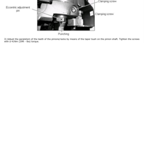
4.1 Mechanic Adjustment Of The Attachment Support Bearings
5.1 Mechanic Stroke End Adjustment
5.2 Rotating Mechanic Stroke End And Cams
5.3 Traslation Speed Reducer Microswitch
6.1 Mechanical Adjustments Of The Load Handler Bearings
7.1 Maintenance
8.1 Troubleshooting
Section: Mast
1.1 Removing The Cab From The Mast
1.0 Mast Removal Procedure Mod. Eu C1.0 – C1.3 – C1.5B – C1.8X Mod. Us V30Xmu – V35Xmu – V40Xmu
2.0 Removing The Cylinders Mod. Eu C1.0 – C1.3 – C1.5B Mod. Us V30Xmu – V35Xmu
2.1 Removing The Mast Mod. Eu C1.0 – C1.3 – C1.5B Mod. Us V30Xmu – V35Xmu
3.0 Removing The Bottom Guide Bearing Of The Inner Mast Section Mod. Eu C1.0 – C1.3 Mod. Us V30Xmu
4.0 Removing The Rollers From The Cab And Inner Telescoping Section Mod. Eu C1.5B – C1.8X Mod. Us V35Xmu – V40Xmu 5.0 Removing Side Rollers From The Mast Mod. Eu C1.5B – C1.8X Mod. Us V35Xmu – V40Xmu
Section: Bilateral Equipment
1.0 Description Of Equipment
1.0.1 Composition
1.0.2 Telescoping Action
1.1 Top Telescoping Section Or Load Platform
1.2 Intermediate Telescoping Section
1.3 Telescoping Section Support
1.4 Telescoping Assembly
1.5 Table Of Components
2.0 Maintenance
2.0.1 How To Dismantle The Equipment
2.0.2 Tightening Torques
2.0.3 Precautions When Using Maintenance Products
2.0.4 Components Requiring Maintenance
2.0.5 Routine Maintenance Operations
2.0.6 Items Not Requiring Relubrication
2.0.7 Symbols
2.0.8 Fault-Finding And Remedies
3.0 Removing The Various Sectors
4.0 Disassembling Equipment
5.0 Removal Procedure
Section: Wheels
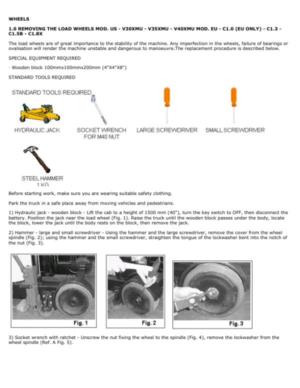
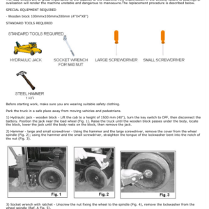
1.0 Removing The Load Wheels
2.0 Removing The Drive Wheels Mod. Us – V30Xmu – V35Xmu Eu – C1.0 (Eu Only) – C1.3 – C1.5B
3.0 Removing The Drive Wheels Mod. Us – V40Xmu Eu – C1.8X
Section: Braking System
1.0 Braking Systems Description
2.0 Removal And Adjustment Of The Electromagnetic Brake
3.0 Adjustment And Putting Into Service
Section: Transmission
1.1 Dismantling The Transmission From The Truck Us – V30Xmu – V35Xmu Eu – C1.0 (Eu Only) – C1.3 – C1.5B
1.2 Introduction
1.3 Dismantling The Connections
1.4 Chain
1.5 Removing The Transmission Unit
1.6 Transmission Oil
1.7 Removing The Motor
1.7A Removing The Plate
1.8 Dismantling The Chain
1.9 Dismantling The Wheel
2.0 Dismantling The Transmission From The Truck Mod. V40Xmu – C1.8X
3.0 General Information V30Xmu – V35Xmu – C1.0 – C1.3 – C1.5B
3.1 Transmission Components
3.2 Consumable Goods
3.4 Standard Tools And Fixtures
4.0 Disassembly
4.1 Introduction
4.2 Removal And Disassembly Of The Transmission Housing Upper Part
4.3 Removing Of The Transmission Cover
4.4 Dismantling The Crown Gear And Wheel Shaft
4.5 Removing The Taper Roller Bearing Inner Race From The Wheel Shaft And Crown Gear
4.6 Disassembly Of The Pinion Shaft
4.7 Disassembly Of The Taper Roller Bearing Outer Race From The Transmission Housing
4.8 Removing The Thread Protective Shield
5.0 Assembly
5.1 Introduction
5.2 Measuring The Assembly Dimension Of The Pinion Shaft
5.3 Pre-Assembly Of The Transmission Housing
5.4 Pre-Assembly Of The Wheel Shaft
5.5 Mounting The Taper Roller Bearing Inner Race On The Crown Gear
5.6 Pre-Assembly Of The Pinion Shaft
5.7 Mounting The Pinion Shaft In The Transmission Housing
5.8 Measuring The Bearing Clearance Of The Pinion Shaft And Adjusting The Pre-Stress
5.9 Mounting The Wheel Shaft And The Crown Gear On The Transmission Housing
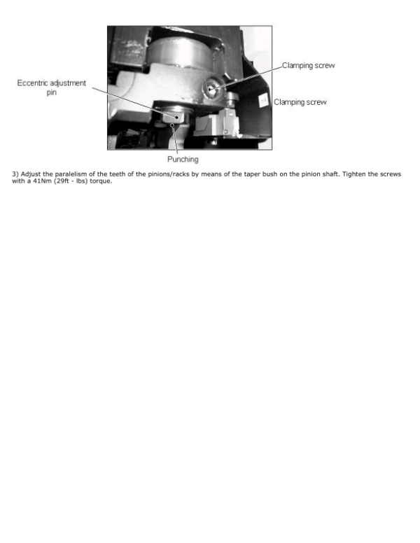
5.10 Measuring And Adjusting The Crown Gear Circumferential Backlash
5.11 Checking The Tooth Pattern
5.12 Measuring The Wheel Shaft Bearing Clearance And Adjusting The Bearing Pre-Stress
5.13 Mounting The Thread Protective Shield In The Transmission Housing
5.14 Mounting The Radial Shaft Seal In The Transmission Housing
5.15 Mounting The Housing Cover
5.16 Transmission Upper Part
6.0 Adjustment Data
6.1 Tightening Torque
7.0 Troubleshooting
8.0 Storage
8.1 Decommissioning
Guide Wire Installation
Reduction Gear
Series Hfk 100 – 200 400 – 600
Series Gr 92 – 96 – 97
Dc-Eps Power Steering And Wire Guidance
Electrical Drawings (C1.5B)
Electrical Drawings (V35Xmu)
Hydraulic Diagram – Electrical Diagrams
The Service Repair Manual are updated on a regular basis, but may not reflect recent design changes to the product. Updated technical service information may be available from our website.
The Service Repair Manual provide general guidelines for maintenance and service of the A468 Series, Models: C1.05B (V35XMU)and are intended for use by trained and experienced technicians. Failure to properly maintain equipment or to follow instructions contained in the Service Manual could result in damage to the products, personal injury, property damage or death.
• When lifting parts or assemblies, make sure all slings, chains, or cables are correctly fastened, and that the load being lifted is balanced. Make sure the crane, cables, and chains have the capacity to support the weight of the load.
• Do not lift heavy parts by hand, use a lifting mechanism.
• Wear safety glasses.
• DISCONNECT THE BATTERY CONNECTOR before doing any maintenance or repair on electric lift trucks. Disconnect the battery ground cable on internal combustion lift trucks.
• Always use correct blocks to prevent the unit from rolling or falling. See HOW TO PUT THE LIFT TRUCK ON BLOCKS in the Operating Manual or the Periodic Maintenance section.
Caution:
• Always fasten a DO NOT OPERATE tag to the controls of the unit when making repairs, or if the unit needs repairs.
• Be sure to follow the WARNING and CAUTION notes in the instructions.
• Gasoline, Liquid Petroleum Gas (LPG), Compressed Natural Gas (CNG), and Diesel fuel are flammable.
• Be sure to follow the necessary safety precautions when handling these fuels and when working on these fuel systems.
• Batteries generate flammable gas when they are being charged. Keep fire and sparks away from the area. Make sure the area is well ventilated.
Be the first to review “Hyster C1.05B, V35XMU Man-Up Turret Trucks A468 Series Repair Manual”
You must be logged in to post a review.


Reviews
There are no reviews yet.